Nissan Versa (N17): Rear regulator
Exploded View
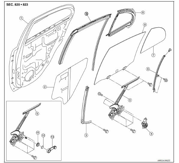
1. Rear door panel 2. Sealing screen 3. Rear door sash 4. Rear power window motor 5. Regulator assembly 6. Partition sash 7. Partition glass 8. Rear door glass 9. Partition weather-strip 10. Rear door glass run 11. Regulator seal (manual window) 12. Retaining clip (manual window) 13. Regulator handle (manual window)
Removal and Installation
REMOVAL
1. Remove rear door glass. Refer to GW "Removal and Installation".
2. Disconnect the harness connector from rear door power window motor.
3. Remove rear door regulator assembly bolts and regulator assembly from rear door panel.
INSTALLATION
Installation is in the reverse order of removal.
Disassembly and Assembly
DISASSEMBLY
Remove the power window motor from the regulator assembly.
INSPECTION AFTER REMOVAL
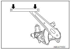
Check the regulator assembly for the following items. Replace or grease it if a malfunction is detected.
- Wire wear
- Regulator deformation
- The arrows show the application points of the multi-purpose grease.
ASSEMBLY
Assembly is in the reverse order of disassembly.
Inspection and Adjustment
FITTING INSPECTION
- Check that the glass fits securely into the sash groove.
- Lower the glass slightly [approximately 10 to 20 mm (0.394 to 0.787 in)], and check that the clearance to the sash is parallel. Loosen the regulator bolts, guide rail bolts, and glass and guide rail bolts to correct the glass position if the clearance between the glass and sash is not parallel.
 Rear door glass
Exploded View 1. Rear door panel 2. Sealing screen 3. Rear door sash 4. Power window motor 5. Regulator assembly 6. Partition sash 7. Partition glass 8. Rear door glass 9. Partition weather-st ...

Other materials:
Seats
WARNING
Do not ride in a moving vehicle when
the seatback is reclined. This can be
dangerous. The shoulder belt will not
be against your body. In an accident,
you could be thrown into it and receive
neck or other serious injuries. You
could also slide under the lap belt and
recei ...
Windows
Power windows (if so equipped)
WARNING
Make sure that all passengers have
their hands, etc. inside the vehicle while
it is in motion and before closing the
windows. Use the window lock switch to
prevent unexpected use of the power
windows
To help avoid risk of injury or death
thr ...
Categories
- Manuals Home
- Nissan Versa Owners Manual
- Nissan Versa Service Manual
- Video Guides
- Questions & Answers
- External Resources
- Latest Updates
- Most Popular
- Sitemap
- Search the site
- Privacy Policy
- Contact Us

0.0055