Nissan Versa (N17): Rear view camera image signal circuit
Diagnosis Procedure
Regarding Wiring Diagram information, refer to AV "Wiring Diagram".
1.CHECK REVERSE INPUT SIGNAL
1. Turn ignition switch ON.
2. Shift the selector lever to R (reverse).
3. Check voltage between AV control unit connector M71 and ground.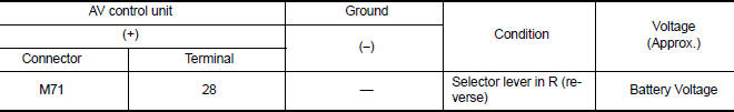
Is inspection result normal?
YES >> GO TO 2.
NO >> Repair or replace harness or connectors.
2.CHECK CAMERA POWER SUPPLY CIRCUIT CONTINUITY
1. Turn ignition switch OFF.
2. Disconnect AV control unit connector M71 and rear view camera connector.
3. Check continuity between AV control unit connector M71 and rear view
camera connector B32.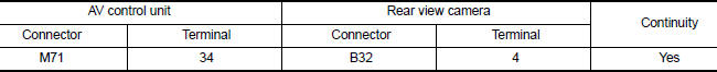
4. Check continuity between AV control unit connector M71 and ground.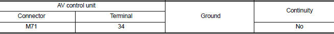
Is inspection result normal?
YES >> GO TO 3.
NO >> Repair or replace harness or connectors.
3.CHECK CAMERA POWER SUPPLY VOLTAGE
1. Connect AV control unit connector M71 and rear view camera connector.
2. Turn ignition switch ON.
3. Shift the selector lever to R (reverse).
4. Check voltage between AV control unit connector M71 and ground.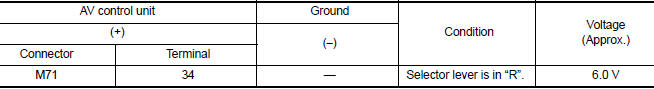
Is inspection result normal?
YES >> GO TO 4.
NO >> Replace AV control unit. Refer to AV "Removal and Installation".
4.CHECK CAMERA IMAGE SIGNAL CIRCUIT CONTINUITY
1. Turn ignition switch OFF.
2. Disconnect AV control unit connector M71 and rear view camera connector.
3. Check continuity between AV control unit connector M71 and rear view
camera connector B32.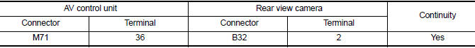
4. Check continuity between AV control unit connector M71 and ground.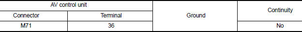
Is inspection result normal?
YES >> GO TO 5.
NO >> Repair or replace harness or connectors.
5.CHECK CAMERA GROUND CIRCUIT CONTINUITY
Check continuity between AV control unit connector M71 and rear view camera
connector B32.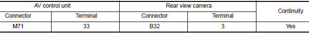
Is inspection result normal?
YES >> GO TO 6.
NO >> Repair or replace harness or connectors.
6.CHECK CAMERA IMAGE SIGNAL
1. Connect AV control unit connector M71 and rear view camera connector.
2. Turn ignition switch ON.
3. Shift the selector lever to R (reverse).
4. Check signal between AV control unit connector M71 and ground.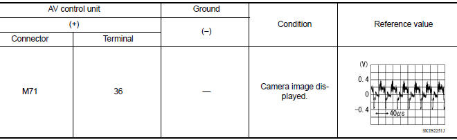
Is inspection result normal?
YES >> Replace AV control unit. Refer to AV "Removal and Installation".
NO >> Replace rear view camera. Refer to AV "Removal and Installation".
 Rear door speaker
Diagnosis Procedure Regarding Wiring Diagram information, refer to AV "Wiring Diagram". 1.CONNECTOR CHECK Check the AV control unit and speaker connectors for the following: Proper ...
Microphone signal circuit
Diagnosis Procedure Regarding Wiring Diagram information, refer to AV "Wiring Diagram". 1.CHECK MICROPHONE SIGNAL CIRCUIT CONTINUITY 1. Turn ignition switch OFF. 2. Disconnect AV control ...
Other materials:
Steering wheel
Tilt operation
Push the lock lever 1 down and adjust the
steering wheel up or down 2 to the desired
position.
Pull the lock lever 1 up to lock the steering
wheel in place.
WARNING
Do not adjust the steering wheel while
driving. You could lose control of your
vehicle and cause an accid ...
P0734 4GR Incorrect ratio
Description
This malfunction is detected when the A/T does not shift into 4GR position as
instructed by TCM. This is not
only caused by electrical malfunction (circuits open or shorted) but by
mechanical malfunction such as control
valve sticking, improper solenoid valve operation, etc.
DTC ...
Categories
- Manuals Home
- Nissan Versa Owners Manual
- Nissan Versa Service Manual
- Video Guides
- Questions & Answers
- External Resources
- Latest Updates
- Most Popular
- Sitemap
- Search the site
- Privacy Policy
- Contact Us

0.0049