Nissan Versa (N17): Microphone signal circuit
Diagnosis Procedure
Regarding Wiring Diagram information, refer to AV "Wiring Diagram".
1.CHECK MICROPHONE SIGNAL CIRCUIT CONTINUITY
1. Turn ignition switch OFF.
2. Disconnect AV control unit connector M71 and microphone connector R15.
3. Check continuity between AV control unit connector M71 and microphone
connector R15.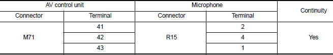
4. Check continuity between AV control unit connector M71 and ground.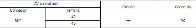
Is inspection result normal?
YES >> GO TO 2.
NO >> Repair or replace harness or connectors.
2.CHECK MICROPHONE VCC VOLTAGE
1. Connect AV control unit connector M71.
2. Turn ignition switch ON.
3. Check voltage between terminals of AV control unit connector M71.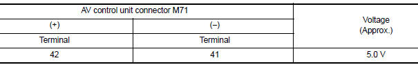
Is the inspection result normal?
YES >> GO TO 3.
NO >> Replace AV control unit. Refer to AV "Removal and Installation".
3.CHECK MICROPHONE SIGNAL
1. Connect microphone connector.
2. Check signal between terminals of AV control unit connector M71.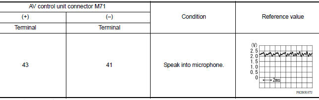
Is the inspection result normal?
YES >> Replace AV control unit. Refer to AV "Removal and Installation".
NO >> Replace microphone. Refer to AV "Removal and Installation".
 Rear view camera image signal circuit
Diagnosis Procedure Regarding Wiring Diagram information, refer to AV "Wiring Diagram". 1.CHECK REVERSE INPUT SIGNAL 1. Turn ignition switch ON. 2. Shift the selector lever to R (reverse ...
Steering switch
Diagnosis Procedure Regarding Wiring Diagram information, refer to AV "Wiring Diagram". 1.CHECK STEERING WHEEL AUDIO CONTROL SWITCH RESISTANCE 1. Turn ignition switch OFF. 2. Disconnect ...
Other materials:
Line pressure control
Line pressure control : system diagram
Line pressure control : system description
When an engine and A/T integrated control signal (engine torque)
equivalent to the engine drive force is
transmitted from the ECM to the TCM, the TCM controls the line pressure
solenoid valve.
Th ...
Coil spring
Exploded View
1. Upper rubber seat 2. Coil spring 3. Lower rubber seat
4. Rear suspension beam
Removal and Installation
REMOVAL
Remove the wheel and tire assemblies using power tool. Refer to WT
"Adjustment".
Position a suitable jack under rear suspension beam.
CAUTION ...
Categories
- Manuals Home
- Nissan Versa Owners Manual
- Nissan Versa Service Manual
- Video Guides
- Questions & Answers
- External Resources
- Latest Updates
- Most Popular
- Sitemap
- Search the site
- Privacy Policy
- Contact Us

0.0048