Nissan Versa (N17): Steering switch
Diagnosis Procedure
Regarding Wiring Diagram information, refer to AV "Wiring Diagram".
1.CHECK STEERING WHEEL AUDIO CONTROL SWITCH RESISTANCE
1. Turn ignition switch OFF.
2. Disconnect combination switch connector M88.
3. Check resistance between the terminals of combination switch connector
M88.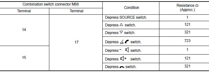
Is the inspection result normal?
YES >> GO TO 2.
NO >> Replace steering switches. Refer to AV "Removal and Installation".
2.CHECK COMBINATION SWITCH
Check continuity between combination switch connectors M88 and M30.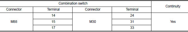
Is the inspection result normal?
YES >> GO TO 3.
NO >> Replace spiral cable. Refer to SR "Removal and Installation".
3.CHECK HARNESS BETWEEN COMBINATION SWITCH AND AV CONTROL UNIT
1. Disconnect AV control unit connector M30.
2. Check continuity between combination switch connector M30 and AV control
unit connector M70.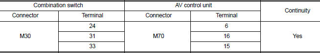
3. Check continuity between combination switch connector M30 and ground.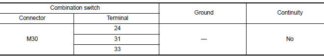
Is the inspection result normal?
YES >> Replace AV control unit. Refer to AV "Removal and Installation".
NO >> Repair or replace harness or connectors.
 Microphone signal circuit
Diagnosis Procedure Regarding Wiring Diagram information, refer to AV "Wiring Diagram". 1.CHECK MICROPHONE SIGNAL CIRCUIT CONTINUITY 1. Turn ignition switch OFF. 2. Disconnect AV control ...
USB Connector
Diagnosis Procedure Regarding Wiring Diagram information, refer to AV "Wiring Diagram". 1.CHECK USB INTERFACE HARNESS CONTINUITY 1. Turn ignition switch OFF. 2. Disconnect AV control uni ...
Other materials:
Recommended fluids/lubricants and capacities
The following are approximate capacities. The actual refill capacities may
be a little different. When refilling, follow the procedure
described in the "Do-it-yourself" section to determine the proper refill
capacity.
...
Readiness for inspection/maintenance (I/M) test
Due to legal requirements in some states and
Canadian Provinces, your vehicle may be required
to be in what is called the "ready condition"
for an Inspection/Maintenance (I/M) test of
the emission control system.
The vehicle is set to the "ready condition" when it
is driven through certain d ...
Categories
- Manuals Home
- Nissan Versa Owners Manual
- Nissan Versa Service Manual
- Video Guides
- Questions & Answers
- External Resources
- Latest Updates
- Most Popular
- Sitemap
- Search the site
- Privacy Policy
- Contact Us

0.0048