Nissan Versa (N17): USB Connector
Diagnosis Procedure
Regarding Wiring Diagram information, refer to AV "Wiring Diagram".
1.CHECK USB INTERFACE HARNESS CONTINUITY
1. Turn ignition switch OFF.
2. Disconnect AV control unit connector M73 and USB interface connector M72.
3. Check continuity between AV control unit connector M73 and USB interface
connector M72.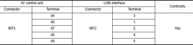
4. Check continuity between AV control unit connector M73 and ground.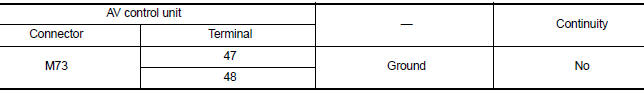
Is the inspection result normal?
YES >> Replace the USB interface. Refer to AV "Removal and Installation".
NO >> Repair or replace harness or connectors.
 Steering switch
Diagnosis Procedure Regarding Wiring Diagram information, refer to AV "Wiring Diagram". 1.CHECK STEERING WHEEL AUDIO CONTROL SWITCH RESISTANCE 1. Turn ignition switch OFF. 2. Disconnect ...
Auxiliary input jack
Diagnosis Procedure Regarding Wiring Diagram information, refer to AV "Wiring Diagram". 1.CHECK AUX JACK HARNESS CONTINUITY 1. Turn ignition switch OFF. 2. Disconnect AV control unit c ...
Other materials:
P0980 Shift solenoid C
DTC Logic
DTC DETECTION LOGIC
DTC
Trouble diagnosis name
DTC detection condition
Possible causes
P0980
Shift Solenoid C Control Circuit
High
The following diagnosis conditions
are met, and the TCM 2-4
brake solenoid valve current
monitor reading is 200 mA ...
Hood lock
HOOD LOCK : Removal and Installation
REMOVAL
Remove hood lock assembly bolts and hood lock assembly.
Disconnect hood lock control cable assembly (2) from hood lock
assembly (1).
INSTALLATION
Installation is in the reverse order of removal.
CAUTION:
Be careful not to bend the cabl ...
Categories
- Manuals Home
- Nissan Versa Owners Manual
- Nissan Versa Service Manual
- Video Guides
- Questions & Answers
- External Resources
- Latest Updates
- Most Popular
- Sitemap
- Search the site
- Privacy Policy
- Contact Us

0.0051