Nissan Versa (N17): Auxiliary input jack
Diagnosis Procedure
Regarding Wiring Diagram information, refer to AV "Wiring Diagram".
1.CHECK AUX JACK HARNESS CONTINUITY
1. Turn ignition switch OFF.
2. Disconnect AV control unit connector M71 and AUX in jack connector M76.
3. Check continuity between AV control unit connector M71 and AUX in jack
connector M76.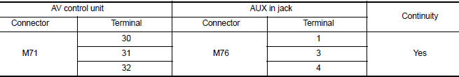
4. Check continuity between AV control unit connector M71 and ground.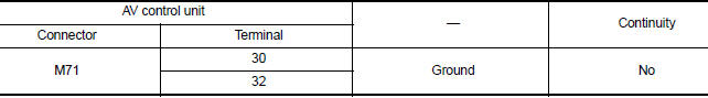
Is the inspection result normal?
YES >> Replace the AUX in jack. Refer to AV "Removal and Installation".
NO >> Repair or replace harness or connectors.
SYMPTOM DIAGNOSIS
 USB Connector
Diagnosis Procedure Regarding Wiring Diagram information, refer to AV "Wiring Diagram". 1.CHECK USB INTERFACE HARNESS CONTINUITY 1. Turn ignition switch OFF. 2. Disconnect AV control uni ...
Multi AV system
Symptom Table RELATED TO AUDIO Symptoms Check items Probable malfunction location The disk cannot be removed. AV control unit Malfunction in AV control unit. Refer t ...
Other materials:
Front oil seal
FRONT OIL SEAL : Removal and Installation
REMOVAL
1. Remove the following parts.
Remove wheel and tire.
Front fender protector (RH).
Drive belt.
Crankshaft pulley.
2. Remove front oil seal with ...
ABS Actuator and electric unit
(control unit)
Exploded View
1. ABS actuator and electric unit (control
unit)
2. ABS actuator and electric unit (control
unit) harness connector
3. Bushing
4. Bracket A. To master cylinder secondary side B. To master cylinder primary
side
C. To front wheel cylinder (LH) D. To rear wheel cylinder (RH ...
Categories
- Manuals Home
- Nissan Versa Owners Manual
- Nissan Versa Service Manual
- Video Guides
- Questions & Answers
- External Resources
- Latest Updates
- Most Popular
- Sitemap
- Search the site
- Privacy Policy
- Contact Us

0.0069