Nissan Versa (N17): Remote keyless entry receiver
Description
Receives keyfob operation and transmits to BCM.
Component Function Check
1.CHECK FUNCTION
With CONSULT
Check remote keyless entry receiver KEYLESS LOCK, KEYLESS UNLOCK, KYLS TRNK/HAT
and KEYLESS PANIC in Data Monitor mode with CONSULT. 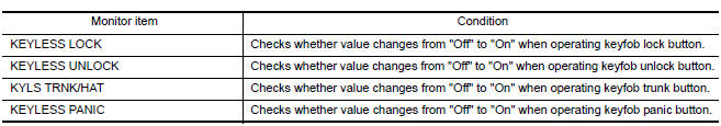
Is the inspection result normal?
YES >> Remote keyless entry receiver is OK.
NO >> Refer to DLK "Diagnosis Procedure".
Diagnosis Procedure
Regarding Wiring Diagram information, refer to DLK "Wiring Diagram".
1.CHECK REMOTE KEYLESS ENTRY RECEIVER OUTPUT SIGNAL
- Turn ignition switch OFF.
- Check signal between remote keyless entry receiver connector and ground
with oscilloscope.
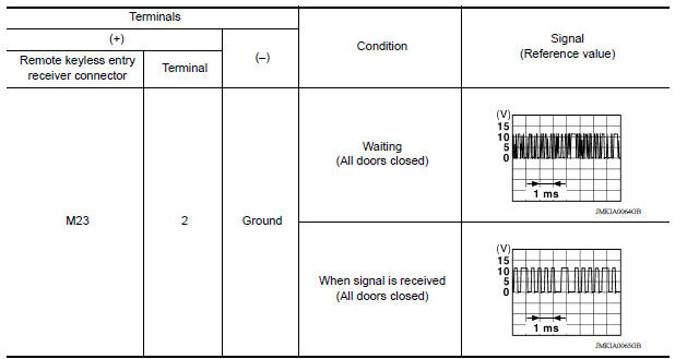
Is the inspection result normal?
YES >> GO TO 7
NO >> GO TO 2
2.CHECK REMOTE KEYLESS ENTRY RECEIVER POWER SUPPLY
- Disconnect remote keyless entry receiver connector.
- Check signal between remote keyless entry receiver connector and ground
with oscilloscope.
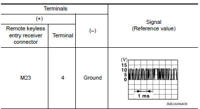
Is the inspection result normal?
YES >> GO TO 4
NO >> GO TO 3
3.CHECK REMOTE KEYLESS ENTRY RECEIVER CIRCUIT 1
- Disconnect BCM connector.
- Check continuity between BCM connector and remote keyless entry receiver
connector.
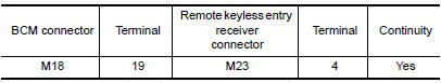
- Check continuity between BCM connector and ground.
Is the inspection result normal?
YES >> Reconnect BCM, GO TO 4
NO >> Repair or replace harness between BCM and remote keyless entry receiver.
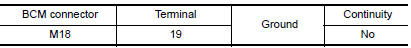
4.CHECK REMOTE KEYLESS ENTRY RECEIVER GROUND CIRCUIT
Check continuity between remote keyless entry receiver connector and ground. 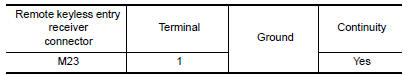
Is the inspection result normal?
YES >> GO TO 6
NO >> GO TO 5
5.CHECK REMOTE KEYLESS ENTRY RECEIVER CIRCUIT 2
Check continuity between BCM connector and remote keyless entry receiver
connector. 
Is the inspection result normal?
YES >> GO TO 7
NO >> Repair or replace harness between BCM and remote keyless entry receiver.
6.CHECK REMOTE KEYLESS ENTRY RECEIVER CIRCUIT 3
1. Check continuity between BCM connector and remote
keyless entry receiver connector. 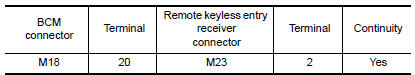
2. Check continuity between BCM connector and ground 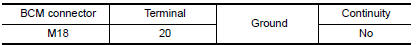
Is the inspection result normal?
YES >> GO TO 7
NO >> Repair or replace harness between BCM and remote keyless entry.
7.CHECK INTERMITTENT INCIDENT
Refer to GI "Intermittent Incident".
>> Inspection End.
 Trunk lid opener actuator
Component Function Check 1.CHECK FUNCTION Press the trunk release button on the keyfob and check that the trunk lid opens. Is the inspection result normal? YES >> Inspection End. NO > ...
Keyfob battery and function
Description The following functions are available when having and carrying the keyfob. Door lock/unlock Panic mode (horn and headlamp operation) Remote control entry function and panic alarm ...
Other materials:
When traveling or registering in another country
When planning to drive your NISSAN vehicle
in another country, you should first find
out if the fuel available is suitable for your vehicle's
engine.
Using fuel with an octane rating that is too low
may cause engine damage. All gasoline vehicles
must be operated with unleaded gasoline. There ...
Automatic speed control device (ASCD)
Automatic speed control device (ascd) : system diagram
NOTE:
Transmission range switch and TCM is also for A/T models.
Automatic speed control device (ascd) : system description
INPUT/OUTPUT SIGNAL CHART
Sensor
Input signal to ECM
ECM function
Actuator
Brake pedal ...
Categories
- Manuals Home
- Nissan Versa Owners Manual
- Nissan Versa Service Manual
- Video Guides
- Questions & Answers
- External Resources
- Latest Updates
- Most Popular
- Sitemap
- Search the site
- Privacy Policy
- Contact Us

0.0054