Nissan Versa (N17): Precautions
Precaution for Supplemental Restraint System (SRS) "AIR BAG" and "SEAT BELT PRE-TENSIONER"
The Supplemental Restraint System such as "AIR BAG" and "SEAT BELT PRE-TENSIONER", used along with a front seat belt, helps to reduce the risk or severity of injury to the driver and front passenger for certain types of collision. This system includes seat belt switch inputs and dual stage front air bag modules. The SRS system uses the seat belt switches to determine the front air bag deployment, and may only deploy one front air bag, depending on the severity of a collision and whether the front occupants are belted or unbelted.
Information necessary to service the system safely is included in the SR and SB section of this Service Manual.
WARNING:
- To avoid rendering the SRS inoperative, which could increase the risk of personal injury or death in the event of a collision which would result in air bag inflation, all maintenance must be performed by an authorized NISSAN/INFINITI dealer.
- Improper maintenance, including incorrect removal and installation of the SRS, can lead to personal injury caused by unintentional activation of the system. For removal of Spiral Cable and Air Bag Module, see the SR section.
- Do not use electrical test equipment on any circuit related to the SRS unless instructed to in this Service Manual. SRS wiring harnesses can be identified by yellow and/or orange harnesses or harness connectors.
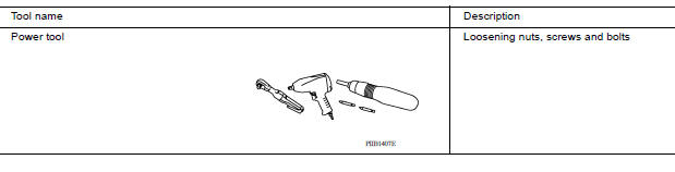
PRECAUTIONS WHEN USING POWER TOOLS (AIR OR ELECTRIC) AND HAMMERS
WARNING:
- When working near the Airbag Diagnosis Sensor Unit or other Airbag System sensors with the Ignition ON or engine running, DO NOT use air or electric power tools or strike near the sensor(s) with a hammer. Heavy vibration could activate the sensor(s) and deploy the air bag(s), possibly causing serious injury.
- When using air or electric power tools or hammers, always switch the Ignition OFF, disconnect the battery, and wait at least 3 minutes before performing any service.
Precaution for Procedure without Cowl Top Cover
When performing the procedure after removing cowl top cover, cover the lower end of windshield with urethane, etc to prevent damage to windshield.
Precaution for Work
- When removing or disassembling each component, be careful not to damage or deform it. If a component may be subject to interference, be sure to protect it with a shop cloth.
- When removing (disengaging) components with a screwdriver or similar tool, be sure to wrap the component with a shop cloth or vinyl tape to protect it.
- Protect the removed parts with a shop cloth and prevent them from being dropped.
- Replace a deformed or damaged clip.
- If a part is specified as a non-reusable part, always replace it with a new one.
- Be sure to tighten bolts and nuts securely to the specified torque.
- After installation is complete, be sure to check that each part works properly.
- Follow the steps below to clean components:
- Water soluble dirt:
- Dip a soft cloth into lukewarm water, wring the water out of the cloth and wipe the dirty area.
- Then rub with a soft, dry cloth.
- Oily dirt:
- Dip a soft cloth into lukewarm water with mild detergent (concentration: within 2 to 3%) and wipe the dirty area.
- Then dip a cloth into fresh water, wring the water out of the cloth and wipe the detergent off.
- Then rub with a soft, dry cloth.
- Do not use organic solvent such as thinner, benzene, alcohol or gasoline.
- For genuine leather seats, use a genuine leather seat cleaner.
Working with HFC-134a (R-134a)
WARNING:
- CFC-12 (R-12) refrigerant and HFC-134a (R-134a) refrigerant are not compatible. If the refrigerants are mixed compressor failure is likely to occur. Refer to HA "Precaution for Working with HFC- 134a (R-134a)". To determine the purity of HFC-134a (R-134a) in the vehicle and recovery tank, use Refrigerant Recovery/Recycling Recharging equipment and Refrigerant Identifier.
- Use only specified oil for the HFC-134a (R-134a) A/C system and HFC-134a (R-134a) components. If oil other than that specified is used, compressor failure is likely to occur.
- The specified HFC-134a (R-134a) oil rapidly absorbs moisture from the atmosphere. The following handling precautions must be observed:
- When removing refrigerant components from a vehicle, immediately cap (seal) the component to minimize the entry of moisture from the atmosphere.
- When installing refrigerant components to a vehicle, do not remove the caps (unseal) until just before connecting the components. Connect all refrigerant loop components as quickly as possible to minimize the entry of moisture into system.
- Only use the specified oil from a sealed container. Immediately reseal containers of oil. Without proper sealing, oil will become moisture saturated and should not be used.
- Avoid breathing A/C refrigerant and oil vapor or mist. Exposure may irritate eyes, nose and throat.
Remove HFC-134a (R-134a) from the A/C system using certified service equipment meeting requirements of SAE J2210 [HFC-134a (R-134a) recycling equipment], or J2209 [HFC-134a (R-134a) recycling equipment]. If accidental system discharge occurs, ventilate work area before resuming service. Additional health and safety information may be obtained from refrigerant and oil manufacturers.
- Do not allow A/C oil to come in contact with styrofoam parts. Damage may result.
CONTAMINATED REFRIGERANT
If a refrigerant other than pure HFC-134a (R-134a) is identified in a vehicle, your options are:
- Explain to the customer that environmental regulations prohibit the release of contaminated refrigerant into the atmosphere.
- Explain that recovery of the contaminated refrigerant could damage your service equipment and refrigerant supply.
- Suggest the customer return the vehicle to the location of previous service where the contamination may have occurred.
- If you choose to perform the repair, recover the refrigerant using only
dedicated equipment and containers.
Do not recover contaminated refrigerant into your existing service equipment. If your facility does not have dedicated recovery equipment, you may contact a local refrigerant product retailer for available service.
This refrigerant must be disposed of in accordance with all federal and local regulations. In addition, replacement of all refrigerant system components on the vehicle is recommended.
- If the vehicle is within the warranty period, the air conditioner warranty is void. Please contact NISSAN Customer Affairs for further assistance.
Service Equipment
RECOVERY/RECYCLING EQUIPMENT
Follow the manufacturer's instructions for machine operation and machine maintenance. Do not introduce any refrigerant other than that specified into the machine.
ELECTRONIC LEAK DETECTOR
Follow the manufacturer's instructions for tester operation and tester maintenance.
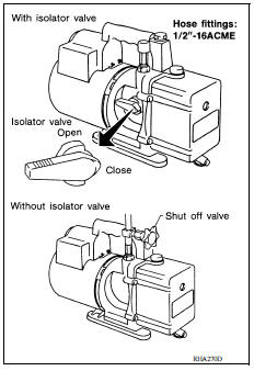
VACUUM PUMP
The oil contained inside the vacuum pump is not compatible with the specified oil for HFC-134a (R-134a) A/C systems. The vent side of the vacuum pump is exposed to atmospheric pressure so the vacuum pump oil may migrate out of the pump into the service hose.
This is possible when the pump is switched off after evacuation (vacuuming) and hose is connected to it.
To prevent this migration, use a manual valve situated near the hose-to-pump connection, as follows.
- Usually vacuum pumps have a manual isolator valve as part of the pump. Close this valve to isolate the service hose from the pump.
- For pumps without an isolator, use a hose equipped with a manual shut-off valve near the pump end. Close the valve to isolate the hose from the pump.
- If the hose has an automatic shut off valve, disconnect the hose from the pump: as long as the hose is connected, the valve is open and lubricating oil may migrate.
Some one-way valves open when vacuum is applied and close under a no vacuum condition. Such valves may restrict the pump's ability to pull a deep vacuum and are not recommended.
MANIFOLD GAUGE SET
Be certain that the gauge face indicates R-134a or 134a. Make sure the gauge set has 1/2″-16 ACME threaded connections for service hoses. Confirm the set has been used only with refrigerant HFC- 134a (R-134a) along with specified oil.
SERVICE HOSES
Be certain that the service hoses display the markings described (colored hose with black stripe). All hoses must include positive shutoff devices (either manual or automatic) near the end of the hoses opposite the manifold gauge.
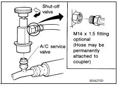
SERVICE COUPLERS
Do not attempt to connect HFC-134a (R-134a) service couplers to a
CFC-12 (R-12) A/C system. The HFC-134a (R-134a) couplers will
not properly connect to the CFC-12 (R-12) system. However, if an
improper connection is attempted, discharging and contamination
may occur. 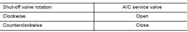
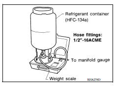
WEIGHT SCALE
Verify that no refrigerant other than HFC-134a (R-134a) and specified oils have been used with the weight scale. If the weight scale controls refrigerant flow electronically, the hose fitting must be 1/2"- 16 ACME.
CHARGING CYLINDER
Using a charging cylinder is not recommended. Refrigerant may be vented into air from cylinder's top valve when filling the cylinder with refrigerant. Also, the accuracy of the cylinder is generally less than that of an electronic scale or of quality recycle/recharge equipment.
PREPARATION
Special Service Tool
The actual shapes of Kent-Moore tools may differ from those of special service tools illustrated here.
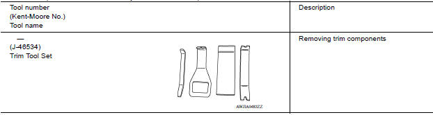
Commercial Service Tool
SYSTEM DESCRIPTION
COMPONENT PARTS
Component Parts Location
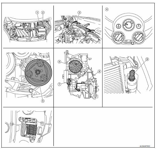
1. IPDM E/R 2. ECM 3. BCM (view with instrument panel removed) 4. Front air control 5. A/C compressor 6. Front blower motor (view with A/C unit assembly removed) 7. Front blower motor resistor (view with A/C unit assembly removed) 8. Thermo control amp. (view with A/C unit assembly removed) 9. Refrigerant pressure sensor 10. Fuse block (J/B) 11. Blower relay
Component Description
| Component | Description |
| A/C compressor | Vaporized refrigerant is drawn into the A/C compressor from the evaporator, where it is compressed to a high pressure, high temperature vapor. The hot, compressed vapor is then discharged to the condenser. |
| BCM | The BCM receives the fan ON and A/C ON signals from the front air control and sends a compressor ON request to the ECM. |
| ECM | The ECM sends a compressor ON request to the IPDM E/R based on the status of engine operation and load as well as refrigerant pressure information. If all the conditions are met for A/C operation, the ECM transmits the compressor ON request to the IPDM E/R. |
| Fuse Block (J/B) | Located in the passenger compartment, behind the left lower IP, the Fuse Block (J/B) contains the front blower motor relay and several fuses required for the air conditioner control system. |
| Front air control | The front air control controls the operation of the A/C and heating system. |
| Front blower motor | The front blower motor varies the speed at which the air flows through the ventilation system. |
| Front blower motor relay | The front blower motor relay controls the flow of current to fuse 20, 21 and 22 in the Fuse Block (J/ B). The relay is connected directly to ground, and is energized when the ignition switch is in the ON or START position. |
| Front blower motor resistor | Ground for the blower is supplied through blower resistor and the blower speed switch. As the switch is moved from position 1 through 5, more current is allowed to flow through the motor, for a higher speed. This is because less resistors are in the path as the switch is moved to a higher position. When the switch is on the highest position, all resistors are bypassed. |
| IPDM E/R | A/C relay is integrated in IPDM E/R. IPDM E/R operates A/C relay when receiving A/C compressor request signal from ECM via CAN communication line. |
| Refrigerant pressure sensor | Refer to EC "Refrigerant Pressure Sensor". |
| Thermo control amp. | Thermo control amp. is composed of thermistor and amplifier. When the A/C switch signal is received from the front air control, the thermo control amp. transmits the A/C ON signal to the BCM according to evaporator fin temperature. When the thermistor detecting temperature of the air that passes through evaporator is extremely low, the thermo control amp. sends the A/C OFF signal to BCM, and stops the compressor. |
SYSTEM
 Evaporator
Removal and Installation REMOVAL Remove A/C unit assembly. Refer to HA "Removal and Installation". Disassemble A/C unit assembly and the evaporator assembly. Remove thermo control a ...
Manual air conditioning system
MANUAL AIR CONDITIONING SYSTEM : System Diagram MANUAL AIR CONDITIONING SYSTEM : System Description The manual air conditioning system is controlled by a sequence of functions from ...
Other materials:
Engine cooling system
The engine cooling system is filled at the factory
with a pre-diluted mixture of 50% Genuine
NISSAN Long Life Antifreeze/Coolant (blue) and
50% water to provide year-round antifreeze and
coolant protection. The antifreeze solution contains
rust and corrosion inhibitors. Additional engine
cooli ...
Fender protector
Exploded View
1. Fender protector 2. J-nut Front
Removal and Installation
REMOVAL
1. Remove under cover. Refer to EXT"Removal and Installation".
2. Remove fender protector screws and clips.
3. Remove fender protector.
INSTALLATION
Installation is in the reverse order of removal ...
Categories
- Manuals Home
- Nissan Versa Owners Manual
- Nissan Versa Service Manual
- Video Guides
- Questions & Answers
- External Resources
- Latest Updates
- Most Popular
- Sitemap
- Search the site
- Privacy Policy
- Contact Us

0.0063