Nissan Versa (N17): Steering switch
Diagnosis Procedure
Regarding Wiring Diagram information, refer to AV "Wiring Diagram".
1.CHECK STEERING WHEEL AUDIO CONTROL SWITCH RESISTANCE
1. Turn ignition switch OFF.
2. Disconnect combination switch connector M88.
3. Check resistance between the terminals of combination switch connector
M88.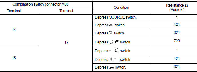
Is the inspection result normal?
YES >> GO TO 2.
NO >> Replace steering switches. Refer to AV "Removal and Installation".
2.CHECK HARNESS BETWEEN BLUETOOTH CONTROL UNIT AND COMBINATION SWITCH
1. Disconnect Bluetooth control unit connector B33 and combination switch connector M30.
2. Check continuity between Bluetooth control unit connector B33 and
combination switch connector M30.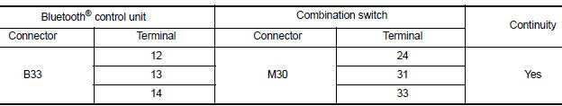
3. Check continuity between Bluetooth control unit connector B33 and ground.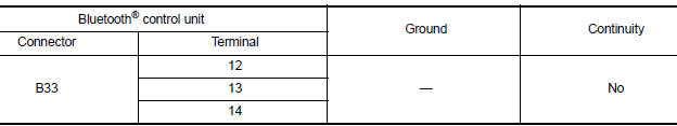
Is the inspection result normal?
YES >> GO TO 3.
NO >> Repair or replace harness or connectors.
3.CHECK COMBINATION SWITCH
Check continuity between combination switch connectors M88 and M30.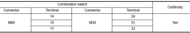
Is the inspection result normal?
YES >> GO TO 4.
NO >> Replace spiral cable. Refer to SR "Removal and Installation".
4.CHECK HARNESS BETWEEN BLUETOOTH CONTROL UNIT AND AUDIO UNIT
1. Disconnect audio unit connector M44.
2. Check continuity between Bluetooth control unit connector B33 and audio
unit connector M44.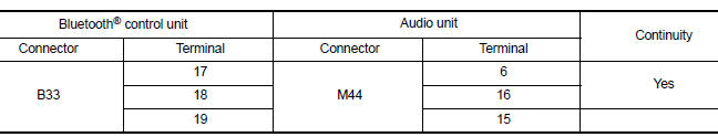
3. Check continuity between Bluetooth control unit connector B33 and ground.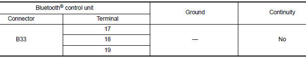
Is the inspection result normal?
YES >> Replace audio unit. Refer to AV "Removal and Installation".
NO >> Repair or replace harness or connectors.
SYMPTOM DIAGNOSIS
 Microphone signal circuit
Diagnosis Procedure Regarding Wiring Diagram information, refer to AV"Wiring Diagram". 1.CHECK HARNESS BETWEEN BLUETOOTH CONTROL UNIT AND MICROPHONE 1. Turn ignition switch OFF. 2. Disco ...
Audio system
Symptom Table RELATED TO AUDIO RELATED TO HANDS-FREE PHONE Before performing diagnosis, confirm that the cellular phone being used by the customer is compatible with the vehicl ...
Other materials:
NISSAN Voice Recognition System (if so equipped)
The NISSAN Voice Recognition system allows
hands-free operation of the systems equipped on
this vehicle, such as the phone and navigation
systems.
To operate NISSAN Voice Recognition, press
the button located on the steering
wheel.
When prompted, speak the command for the
system you wi ...
Variable voltage control system (if so equipped)
CAUTION
Do not ground accessories directly to
the battery terminal. Doing so will bypass
the variable voltage control system
and the vehicle battery may not
charge completely.
Use electrical accessories with the engine
running to avoid discharging the
vehicle battery.
Your v ...
Categories
- Manuals Home
- Nissan Versa Owners Manual
- Nissan Versa Service Manual
- Video Guides
- Questions & Answers
- External Resources
- Latest Updates
- Most Popular
- Sitemap
- Search the site
- Privacy Policy
- Contact Us

0.0054