Nissan Versa (N17): Trunk room lamp circuit
Description
Controls the trunk room lamp (ground side) to turn the trunk room lamp ON and OFF.
Component Function Check
CAUTION: Before performing the diagnosis, check that the following is normal.
- Battery saver output/power supply
- Trunk room lamp bulb
Diagnosis Procedure
Regarding Wiring Diagram information, refer to INL "Wiring Diagram".
1.CHECK TRUNK ROOM LAMP OUTPUT
1. Turn ignition switch OFF.
2. Remove the trunk room bulb.
3. Check continuity between BCM harness connector and ground.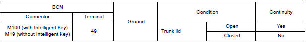
Is the inspection result normal?
YES >> GO TO 2.
Fixed ON>>GO TO 3.
Fixed OFF>>Replace BCM after making sure battery saver output/power supply circuit is not shorted to voltage.
Refer to BCS "Removal and Installation" (with Intelligent Key) or BCS "Removal and Installation" (without Intelligent Key).
2.CHECK TRUNK ROOM LAMP OPEN CIRCUIT
Check continuity between BCM harness connector and trunk room lamp harness
connector.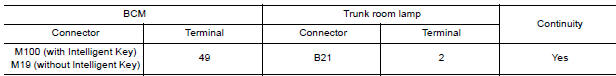
Is the inspection result normal?
YES >> Replace trunk room lamp.
NO >> Repair or replace the harness or connector.
3.CHECK TRUNK ROOM LAMP SHORT CIRCUIT
1. Disconnect BCM harness connector.
2. Check continuity between BCM harness connector and ground.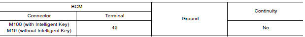
Is the inspection result normal?
YES >> Replace BCM after making sure battery saver output/power supply circuit is not shorted to voltage.
Refer to BCS "Removal and Installation" (with Intelligent Key) or BCS "Removal and Installation" (without Intelligent Key).
NO >> Repair or replace the harness or connector.
 Interior room lamp control circuit
Description Controls each interior room lamp (ground side) by PWM signal. NOTE: PWM signal control period is approximately 250 Hz (in the gradual brightening/dimming). ...
Push-button ignition switch illumination
circuit
Description Provides the power supply and the ground to control the push-button ignition switch illumination. ...
Other materials:
Recommended fluids/lubricants and capacities
The following are approximate capacities. The actual refill capacities may
be a little different. When refilling, follow the procedure
described in the "Do-it-yourself" section to determine the proper refill
capacity.
...
Exhaust system
Exploded View
1. Heated oxygen sensor 2 2. Catalyst cover (upper) 3. Seal bearing
4. Catalyst cover (lower) 5. Spring 6. Spring
7. Mounting rubber 8. Main muffler 9. Ring gasket
10. Center muffler 11. Mounting rubber 12. Seal bearing
13. Exhaust front tube
Removal and Installation
WARNIN ...
Categories
- Manuals Home
- Nissan Versa Owners Manual
- Nissan Versa Service Manual
- Video Guides
- Questions & Answers
- External Resources
- Latest Updates
- Most Popular
- Sitemap
- Search the site
- Privacy Policy
- Contact Us

0.0068