Nissan Versa (N17): Parking brake switch signal circuit
Type A
TYPE A : Description
Transmits the parking brake switch signal to the combination meter.
TYPE A : Component Function Check
1.COMBINATION METER INPUT SIGNAL
1. Select "METER/M&A" on CONSULT.
2. Monitor "PKB SW" of "DATA MONITOR" while applying and releasing the parking brake.
PKB SW
Parking brake depressed : ON
Parking brake released : OFF
Is the inspection result normal?
YES >> Inspection End.
NO >> Refer to WCS "TYPE A : Diagnosis Procedure".
TYPE A : Diagnosis Procedure
Regarding Wiring Diagram information, refer to WCS "Wiring Diagram".
1.CHECK COMBINATION METER INPUT SIGNAL
1. Turn ignition switch ON.
2. Check the voltage between combination meter harness connector and ground.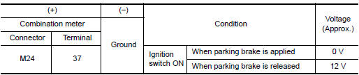
Is the inspection result normal?
YES >> Inspection End.
NO >> GO TO 2.
2.CHECK PARKING BRAKE SWITCH SIGNAL CIRCUIT
1. Turn ignition switch OFF.
2. Disconnect combination meter connector and parking brake switch connector.
3. Check continuity between combination meter harness connector and parking
brake switch harness connector.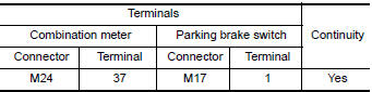
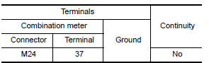
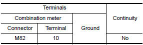
4. Check continuity between combination meter harness connector and ground.
Is the inspection result normal?
YES >> Inspection End.
NO >> Repair harness or connector.
TYPE A : Component Inspection
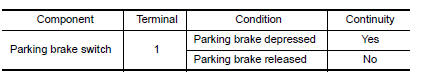
1.CHECK PARKING BRAKE SWITCH
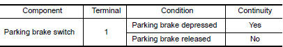
Check continuity between parking brake switch terminal 1 and switch case
ground.
Is the inspection result normal?
YES >> Inspection End.
NO >> Replace parking brake switch.
Type B
TYPE B : Description
Transmits the parking brake switch signal to the combination meter.
TYPE B : Component Function Check
1.COMBINATION METER INPUT SIGNAL
1. Select "METER/M&A" on CONSULT.
2. Monitor "PKB SW" of "DATA MONITOR" while applying and releasing the parking brake.
PKB SW
Parking brake depressed : ON
Parking brake released : OFF
Is the inspection result normal?
YES >> Inspection End.
NO >> Refer to WCS "TYPE B : Diagnosis Procedure".
TYPE B : Diagnosis Procedure
Regarding Wiring Diagram information, refer to WCS "Wiring Diagram".
1.CHECK COMBINATION METER INPUT SIGNAL
1. Turn ignition switch ON.
2. Check the voltage between combination meter harness connector and ground.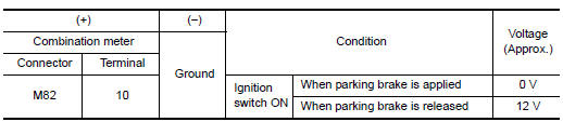
Is the inspection result normal?
YES >> Inspection End.
NO >> GO TO 2.
2.CHECK PARKING BRAKE SWITCH SIGNAL CIRCUIT
1. Turn ignition switch OFF.
2. Disconnect combination meter connector and parking brake switch connector.
3. Check continuity between combination meter harness connector and parking
brake switch harness connector.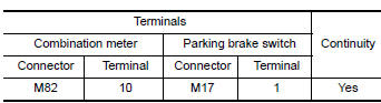
4. Check continuity between combination meter harness connector and ground.
Is the inspection result normal?
YES >> Inspection End.
NO >> Repair harness or connector.
TYPE B : Component Inspection
1.CHECK PARKING BRAKE SWITCH
Check continuity between parking brake switch terminal 1 and switch case
ground.
Is the inspection result normal?
YES >> Inspection End.
NO >> Replace parking brake switch.
SYMPTOM DIAGNOSIS
 Key switch signal circuit (without
intelligent key)
Key switch signal circuit (without
intelligent key)
Description Transmits a key switch signal to the BCM. Component Function Check 1. CHECK BCM INPUT SIGNAL Select "DATA MONITOR" for "BCM" and check the "KEY ON SW" monitor value. KEY ON SW ...
The parking brake release warning
continues sounding, or does not
sound
Description The parking brake warning buzzer sounds continuously during vehicle travel though the parking brake is released. The parking brake warning buzzer does not sound at all even thou ...
Other materials:
Seats
WARNING
Do not ride in a moving vehicle when
the seatback is reclined. This can be
dangerous. The shoulder belt will not
be against your body. In an accident,
you could be thrown into it and receive
neck or other serious injuries. You
could also slide under the lap belt and
recei ...
Spark plug
Exploded View
1. Ignition coil 2. Spark plug
Removal and Installation
REMOVAL
1. Remove ignition coil.
CAUTION:
Do not drop or shock ignition coil.
2. Remove spark plug using a suitable tool.
Diameter (a) : 14 mm (0.55 in)
CAUTION:
Do not drop or shock spark plug.
INSPECTION AFTER REM ...
Categories
- Manuals Home
- Nissan Versa Owners Manual
- Nissan Versa Service Manual
- Video Guides
- Questions & Answers
- External Resources
- Latest Updates
- Most Popular
- Sitemap
- Search the site
- Privacy Policy
- Contact Us

0.006