Nissan Versa (N17): U1000 CAN Comm circuit
Description
Refer to LAN "CAN COMMUNICATION SYSTEM : System Description".
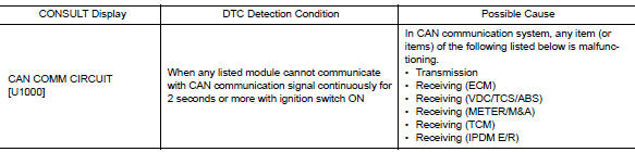
DTC Logic
DTC DETECTION LOGIC
NOTE:
U1000 can be set if a module harness was disconnected and reconnected, perhaps
during a repair. Confirm
that there are actual CAN diagnostic symptoms and a present DTC by performing
the Self Diagnostic Result
procedure.
Diagnosis Procedure
1. PERFORM SELF DIAGNOSTIC RESULT
1. Turn ignition switch ON and wait for 2 second or more.
2. Check "SELF- DIAG RESULTS".
Is "CAN COMM CIRCUIT" displayed?
YES >> Perform CAN Diagnosis as described in DIAGNOSIS section of CONSULT Operation manual.
NO >> Refer to GI "Intermittent Incident".
 Inspection and adjustment
U1010 Control unit (CAN)
DTC Logic DTC DETECTION LOGIC Diagnosis Procedure 1.REPLACE BCM When DTC "U1010" is detected, replace B ...
Other materials:
Oil pump
Exploded View
1. Rear oil seal 2. Oring 3. Oil pan (upper)
4. Oil pump chain tensioner (for oil
pump drive chain)
5. Oil pump drive chain 6. Crankshaft key
7. Crankshaft sprocket 8. Oil pump sprocket 9. Oil pump
10. Oring 11. Oring 12. Oil pan drain plug
13. Drain plug washer 14. Oil pan ( ...
Unbalance steering wheel turning force (torque variation)
Description
Unbalance steering wheel turning force (torque variation).
Diagnosis Procedure
1.PERFORM SELF-DIAGNOSIS
With CONSULT
Turn the ignition switch OFF to ON.
Perform "EPS" self-diagnosis.
Is any DTC detected?
YES >> Check the DTC. Refer to STC "DTC Index".
NO & ...
Categories
- Manuals Home
- Nissan Versa Owners Manual
- Nissan Versa Service Manual
- Video Guides
- Questions & Answers
- External Resources
- Latest Updates
- Most Popular
- Sitemap
- Search the site
- Privacy Policy
- Contact Us

0.0054