Nissan Versa (N17): U1244 GPS Antenna
DTC Logic
DTC DETECTION LOGIC
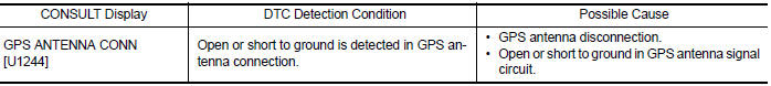
Diagnosis Procedure
Regarding Wiring Diagram information, refer to AV "Wiring Diagram".
1.GPS ANTENNA INSPECTION
Visually inspect the GPS antenna and antenna feeder. Refer to AV "Removal and Installation".
Is inspection result normal?
YES >> GO TO 2.
NO >> Repair or replace malfunctioning components.
2.CHECK AV CONTROL UNIT VOLTAGE
1. Disconnect AV control unit connector M91.
2. Turn ignition switch ON.
3. Check voltage between AV control unit connector M91 and ground.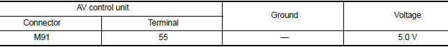
Is inspection result normal?
YES >> Replace GPS antenna. Refer to AV "Removal and Installation".
NO >> Replace AV control unit. Refer to AV "Removal and Installation".
 U1000 CAN Comm circuit
DTC Logic DTC DETECTION LOGIC Diagnosis Procedure 1.PERFORM SELF DIAGNOSTIC RESULT 1. Turn ignition switch ON and wait for 2 seconds or more. 2. Perform Self Diagnostic Result for MULTI AV. Is C ...
U1258 Satellite radio antenna
DTC Logic DTC DETECTION LOGIC Diagnosis Procedure Regarding Wiring Diagram information, refer to AV "Wiring Diagram". 1.SATELLITE ANTENNA INSPECTION Visually inspect ...
Other materials:
Camshaft valve clearance
Inspection and Adjustment
INSPECTION
Perform inspection as follows after removal, replacement or installation of
camshaft or valverelated parts, or if
there are unusual engine conditions regarding valve clearance.
Remove rocker cover.
Measure the valve clearance with the following proced ...
Hood lock control cable
HOOD LOCK CONTROL CABLE : Removal and
Installation
REMOVAL
Disconnect hood lock control cable assembly from hood lock assembly.
Refer to DLK "HOOD LOCK
: Removal and Installation".
Remove fender protector (LH). Refer to EXT "Removal and Installation".
Release hoo ...
Categories
- Manuals Home
- Nissan Versa Owners Manual
- Nissan Versa Service Manual
- Video Guides
- Questions & Answers
- External Resources
- Latest Updates
- Most Popular
- Sitemap
- Search the site
- Privacy Policy
- Contact Us

0.0052