
Nissan Versa (N17): Washer switch
Description
- Washer switch is integrated with combination switch.
- Washer switch supplies ground for the front washer motor.
Component Inspection
1. CHECK WASHER SWITCH
1. Turn the ignition switch OFF.
2. Disconnect combination switch (wiper and washer switch).
3. Check continuity between the combination switch (wiper and washer switch)
terminals.
Is the inspection result normal?
YES >> Washer switch is normal.
NO >> Replace combination switch (wiper and washer switch). Refer to WW "Removal and Installation".
SYMPTOM DIAGNOSIS
WIPER AND WASHER SYSTEM SYMPTOMS
Symptom Table
CAUTION: Perform the self-diagnosis with CONSULT before performing the diagnosis by symptom. Perform the diagnosis by DTC if DTC is detected.
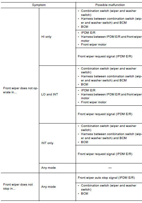
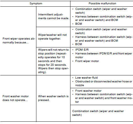
 Washer motor circuit
Diagnosis Procedure Regarding Wiring Diagram information, refer to WW "Wiring Diagram". 1. CHECK FRONT WASHER MOTOR FUSE 1. Turn the ignition switch OFF. 2. Check that the following fuse ...
Front wiper does not operate
Description The front wiper does not operate under any operation conditions. Diagnosis Procedure Regarding Wiring Diagram information, refer to WW "Wiring Diagram". 1. CHECK WIPER RELAY ...
Other materials:
Steering wheel
Tilt operation
Push the lock lever 1 down and adjust the
steering wheel up or down 2 to the desired
position.
Pull the lock lever 1 up to lock the steering
wheel in place.
WARNING
Do not adjust the steering wheel while
driving. You could lose control of your
vehicle and cause an accid ...
Clutch pedal
Exploded View
1. Clutch pedal 2. Pedal stopper rubber 3. Pedal pad
4. Clip 5. Clutch interlock switch
Removal and Installation
REMOVAL
Remove the instrument lower panel LH. Refer to IP, "Removal and
Installation".
Disconnect master cylinder rod end from clutch pedal.
D ...
Categories
- Manuals Home
- Nissan Versa Owners Manual
- Nissan Versa Service Manual
- Video Guides
- Questions & Answers
- External Resources
- Latest Updates
- Most Popular
- Sitemap
- Search the site
- Privacy Policy
- Contact Us

0.0243