
Nissan Versa (N17): Wiper drive assembly
Wiper drive assembly: Removal and Installation
EXPLODED VIEW
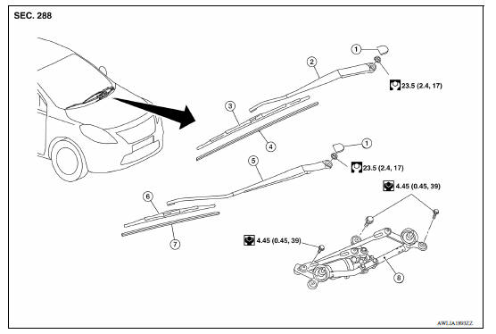
1. Wiper arm cap 2. Wiper arm (LH) 3. Wiper blade (LH) 4. Wiper refill (LH) 5. Wiper arm (RH) 6. Wiper blade (RH) 7. Wiper refill (RH) 8. Wiper drive assembly
REMOVAL
1. Remove cowl top cover. Refer to EXT "Removal and Installation".
2. Disconnect the harness connector from the wiper motor.
3. Remove the wiper drive assembly bolts.
4. Remove wiper drive assembly from the vehicle.
INSTALLATION
Installation is in the reverse order of removal.
Wiper drive assembly : Disassembly and Assembly
EXPLODED VIEW
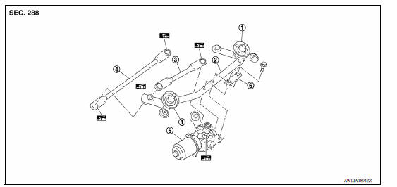
1. Shaft seal 2. Wiper frame 3. Wiper linkage 1 4. Wiper linkage 2 5. Wiper motor assembly 6. Wiper motor assembly bracket
DISASSEMBLY
1. Remove wiper linkage 1 and wiper linkage 2 from the wiper frame.
CAUTION: Do not bend the linkage or damage the plastic part of the ball joint when removing the wiper linkage.
2. Remove wiper motor screws.
3. Remove the wiper motor from the wiper frame.
ASSEMBLY
1. Connect the harness connector to the wiper motor.
2. Operate wiper to move it to the auto stop position.
3. Disconnect the harness connector from the wiper motor.
4. Install wiper motor to wiper frame.
5. Install wiper linkage 1 to the wiper motor and the wiper frame.
6. Install wiper linkage 2 to the wiper frame.
CAUTION:
- Do not drop wiper motor or cause it to come into contact with other parts.
- Be careful of the grease condition at the wiper motor and wiper linkage joint (retainer). Apply multi−purpose grease or an equivalent if necessary.
 Wiper refill
WIPER REFILL : Removal and Installation REMOVAL 1. Remove wiper blade from the wiper arm. Refer to WW "WIPER BLADE : Removal and Installation". 2. From portion (A) of wiper refill (1), ...
Washer tank
Exploded View 1. Washer tank inlet cap 2. Washer tank assembly Front Removal and Installation REMOVAL 1. Remove fender protector. Refer to EXT "Removal and Installation". 2. Di ...
Other materials:
P0713 Transmission fluid temperature
sensor A
DTC Logic
DTC DETECTION LOGIC
DTC
Trouble diagnosis name
DTC detection condition
Possible causes
P0713
Transmission Fluid Temperature
Sensor "A" Circuit High
Under the following diagnosis
conditions, the A/T fluid temperature
identified by TCM is −
...
Parking brake control
Exploded View
1. Parking brake lever assembly 2. Adjusting nut 3. Parking brake switch
4. Front cable 5. Rear cable (LH) 6. Rear cable (RH)
Removal and Installation
REMOVAL
Remove rear wheel and tire assemblies using power tool. Refer to WT
"Adjustment".
Remove the center ...
Categories
- Manuals Home
- Nissan Versa Owners Manual
- Nissan Versa Service Manual
- Video Guides
- Questions & Answers
- External Resources
- Latest Updates
- Most Popular
- Sitemap
- Search the site
- Privacy Policy
- Contact Us

0.0077