Nissan Versa (N17): Parking brake control
Exploded View
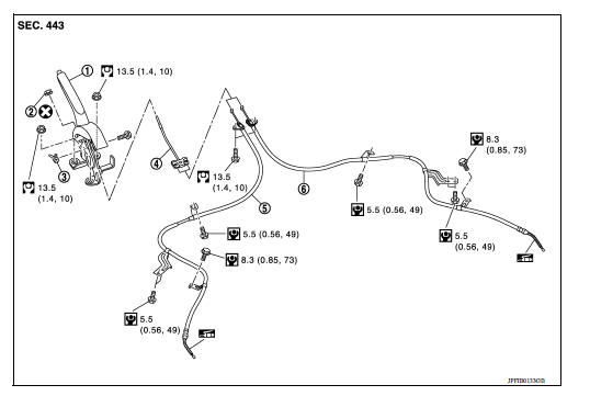
1. Parking brake lever assembly 2. Adjusting nut 3. Parking brake switch 4. Front cable 5. Rear cable (LH) 6. Rear cable (RH)
Removal and Installation
REMOVAL
- Remove rear wheel and tire assemblies using power tool. Refer to WT "Adjustment".
- Remove the center console assembly. Refer to IP "Removal and Installation".
- Disconnect the harness connector from the parking brake switch.
- Remove and discard the adjusting nut to loosen the front cable.
CAUTION: Do not reuse the adjusting nut.
- Separate both rear cables from the front cable.
- Remove the parking brake lever assembly and front cable.
- Remove the front cable from parking brake lever assembly.
- Remove the parking brake switch from parking brake lever assembly.
- Remove both rear cables from the toggle lever.
- Remove the center floor insulator to gain access to the rear cable bolts.
- Remove the brake shoes and disconnect the rear cables from the toggle levers. Refer to BR "Removal and Installation".
- Disconnect and remove the rear cables from each backing plate.
INSTALLATION
Installation is in the reverse order of the removal.
CAUTION: Do not reuse the adjusting nut.
- Perform adjustment after installation. Refer to PB "Inspection and Adjustment".
SERVICE DATA AND SPECIFICATIONS (SDS)
Parking Brake Control
 Parking brake system
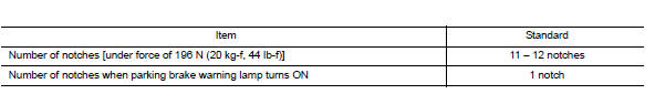
Inspection and Adjustment INSPECTION When parking brake lever is operated with a force of 196 N (20 kg-f, 44 lb-f), make sure parking brake lever stroke is within the specified number of notches. ...

Other materials:
P0740 Torque converter
DTC Logic
DTC DETECTION LOGIC
DTC
Trouble diagnosis name
DTC detection condition
Possible causes
P0740
Torque Converter Clutch Circuit/
Open
The follow diagnosis conditions
are met, and the TCM torque
converter clutch solenoid valve
current monitor readin ...
U1000 CAN Comm circuit
Description
CAN (Controller Area Network) is a serial communication line for real time
application. It is an on-vehicle multiplex
communication line with high data communication speed and excellent error
detection ability. Many electronic
control units are equipped onto a vehicle, and each c ...
Categories
- Manuals Home
- Nissan Versa Owners Manual
- Nissan Versa Service Manual
- Video Guides
- Questions & Answers
- External Resources
- Latest Updates
- Most Popular
- Sitemap
- Search the site
- Privacy Policy
- Contact Us

0.0056