
Nissan Versa (N17): Parking brake system
Inspection and Adjustment
INSPECTION
When parking brake lever is operated with a force of 196 N (20 kg-f, 44 lb-f), make sure parking brake lever stroke is within the specified number of notches. (Check it by listening and counting ratchet clicks.)
Number of notches : Refer to PB "Parking Brake Control".
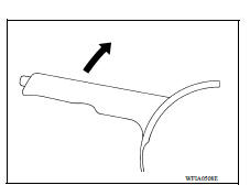
ADJUSTMENT
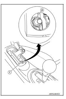
- Pull parking brake lever until the access hole (1) is visible. Insert a socket wrench onto the adjusting nut (A).
- Turn the adjusting nut with a socket wrench to loosen the front cable.
- Depress the brake pedal with a force of 196 N (20 kg-f, 44 lb-f) about
10 times and adjust the brake shoe
clearance.
CAUTION: Make sure to securely operate the brake pedal.
- Check inner diameter of rear brake drum. Refer to BR "BRAKE DRUM : Inspection and Adjustment".
- Adjust the cable with the following procedure.
a. Operate the parking brake lever with a force of 400 N (41 kg-f, 90 lb-f) for 25 minutes or longer.
b. Adjust the parking brake lever stroke by turning the adjusting nut with a socket wrench.
CAUTION: Do not reuse the adjusting nut if the nut is removed.
c. Operate the parking brake lever with a force of 196 N (20 kg-f, 44 lb-f). Check that the lever stroke is within the specified number of notches. (Check it by listening to the clicks of the ratchet.)
Number of notches : Refer to PB"Parking Brake Control".
d. Rotate the brake drum with the parking brake lever released and verify that there is no drag present. Refer to BR "BRAKE DRUM : Inspection and Adjustment".
REMOVAL AND INSTALLATION
 Precautions
Precaution for Supplemental Restraint System (SRS) "AIR BAG" and "SEAT BELT PRE-TENSIONER" The Supplemental Restraint System such as "AIR BAG" and "SEAT BELT PRE-TENSIONER", us ...
Parking brake control
Exploded View 1. Parking brake lever assembly 2. Adjusting nut 3. Parking brake switch 4. Front cable 5. Rear cable (LH) 6. Rear cable (RH) Removal and Installation REMOVAL Remove rear wh ...
Other materials:
Structure and operation
TRANSAXLE
TRANSAXLE : Cross-Sectional View
1. Converter housing 2. Oil pump 3. Counter drive gear
4. Control valve 5. Oil pan 6. Primary pulley
7. Steel belt 8. Secondary pulley 9. Planetary gear (auxiliary gearbox)
10. Side cover 11. Transaxle case 12. Differential case
13. Final gear ...
U0141 Lost communication (BCM A)
Description
CAN (Controller Area Network) is a serial communication line for real-time
application. It is an on-vehicle multiplex
communication line with high data communication speed and excellent malfunction
detection ability.
Many electronic control units are equipped onto a vehicle, and ...
Categories
- Manuals Home
- Nissan Versa Owners Manual
- Nissan Versa Service Manual
- Video Guides
- Questions & Answers
- External Resources
- Latest Updates
- Most Popular
- Sitemap
- Search the site
- Privacy Policy
- Contact Us

0.0056