Nissan Versa (N17): B26F6 BCM
DTC Logic
DTC DETECTION LOGIC
NOTE:
- If DTC B26F6 is displayed with DTC U1000, first perform the trouble diagnosis for DTC U1000. Refer to PCS "DTC Logic".
- If DTC B26F6 is displayed with DTC U1010, first perform the trouble
diagnosis for DTC U1010. Refer to
PCS "DTC Logic".

DTC CONFIRMATION PROCEDURE
1.PERFORM DTC CONFIRMATION PROCEDURE
1. Turn ignition switch ON, and wait for 0.5 seconds or more.
2. Check "Self-diagnosis result" of BCM with CONSULT.
Is DTC detected?
YES >> Go to PCS "Diagnosis Procedure".
NO >> Inspection End.
Diagnosis Procedure
Regarding Wiring Diagram information, refer to PCS "Wiring Diagram".
1. CHECK SELF DIAGNOSTIC RESULT FOR IPDM E/R
Perform self diagnostic result for IPDM E/R.
Are any DTCs detected?
YES >> Refer to PCS"DTC Index".
NO >> GO TO 2
2. CHECK IGNITION RELAY-1 POWER SUPPLY (IPDM E/R)
Check voltage between IPDM E/R connector E47 terminal 90 and ground.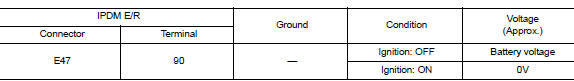
Is the inspection result normal?
YES >> Replace IPDM E/R. Refer to PCS "Removal and Installation".
NO >> GO TO 3.
3. CHECK IGNITION RELAY-1 POWER SUPPLY (BCM)
Check voltage between BCM connector M98 terminal 98 and ground.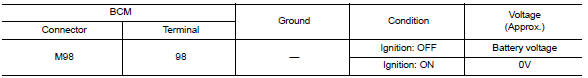
Is the inspection result normal?
YES >> Refer to GI "Intermittent Incident".
NO >> Replace BCM. Refer to BCS "Removal and Installation".
 B26F2 Ignition relay
Other materials:
Security systems (if so equipped)
Your vehicle has one type of security systems:
NISSAN Vehicle Immobilizer System
NISSAN vehicle immobilizer system
The NISSAN Vehicle Immobilizer System will not
allow the engine to start without the use of a
registered key.
If the engine fails to start using a registered key
(for ex ...
Starting the engine (models without NISSAN Intelligent Key system)
1. Apply the parking brake.
2. Automatic Transmission / CVT models:
Move the shift lever to P (Park) or N (Neutral).
P (Park) is recommended.
The shift lever cannot be moved out of
P (Park) and into any of the other gear
positions if the ignition key is turned to
the OFF position or if ...
Categories
- Manuals Home
- Nissan Versa Owners Manual
- Nissan Versa Service Manual
- Video Guides
- Questions & Answers
- External Resources
- Latest Updates
- Most Popular
- Sitemap
- Search the site
- Privacy Policy
- Contact Us

0.0055