Nissan Versa (N17): Power supply and ground circuit
Combination meter
COMBINATION METER : Diagnosis Procedure
Regarding Wiring Diagram information, refer to MWI "Wiring Diagram".
1.CHECK FUSE
Check for blown combination meter fuses. 
Is the inspection result normal?
YES >> GO TO 2.
NO >> Replace the fuse after repairing the affected circuit.
2.POWER SUPPLY CIRCUIT CHECK
1. Disconnect combination meter connector.
2. Check voltage between combination meter harness connector M82, terminals
27, 28, 15 and ground.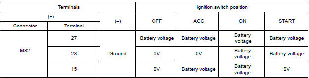
Is the inspection result normal?
YES >> GO TO 3.
NO >> Check harness for open between combination meter and fuse.
3.GROUND CIRCUIT CHECK
1. Turn ignition switch OFF.
2. Disconnect combination meter connector.
3. Check continuity between combination meter harness connector M82,
terminals 21, 22, 23 and ground.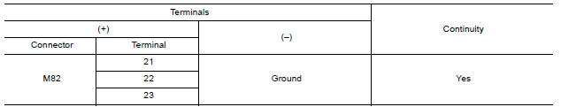
Is the inspection result normal?
YES >> Inspection End.
NO >> Check ground harness.
BCM (Body control system) (with intelligent key system)
BCM (BODY CONTROL SYSTEM) (WITH INTELLIGENT KEY SYSTEM) : Diagnosis Procedure
Regarding Wiring Diagram information, refer to BCS "Wiring Diagram".
1.CHECK FUSES AND FUSIBLE LINK
Check that the following fuses and fusible link are not blown. 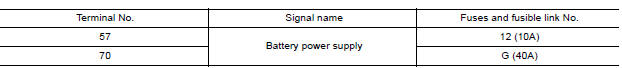
Is the fuse blown?
YES >> Replace the blown fuse or fusible link after repairing the affected circuit.
NO >> GO TO 2.
2.CHECK POWER SUPPLY CIRCUIT
1. Disconnect BCM connector M99.
2. Check voltage between BCM connector M99 and ground.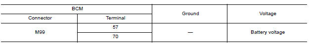
Is the inspection result normal?
YES >> GO TO 3.
NO >> Repair harness or connector.
3.CHECK GROUND CIRCUIT
Check continuity between BCM connector M99 and ground.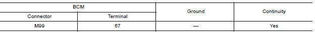
Is the inspection result normal?
YES >> Inspection End.
NO >> Repair harness or connector.
BCM (Body control system) (without intelligent key system)
BCM (BODY CONTROL SYSTEM) (WITHOUT INTELLIGENT KEY SYSTEM) : Diagnosis Procedure
Regarding Wiring Diagram information, refer to BCS "Wiring Diagram".
1.CHECK FUSES AND FUSIBLE LINK
Check that the following fuses and fusible link are not blown.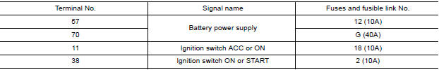
Is the fuse blown?
YES >> Replace the blown fuse or fusible link after repairing the affected circuit.
NO >> GO TO 2.
2.CHECK POWER SUPPLY CIRCUIT
1. Turn ignition switch OFF.
2. Disconnect BCM connectors.
3. Check voltage between BCM connector and ground.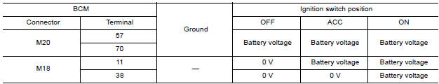
Is the inspection result normal?
YES >> GO TO 3.
NO >> Repair harness or connector.
3.CHECK GROUND CIRCUIT
Check continuity between BCM connector and ground. 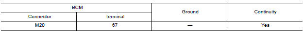
Is the inspection result normal?
YES >> Inspection End.
NO >> Repair harness or connector.
 B2267 Engine speed
Description The engine speed signal is transmitted from ECM to the combination meter via CAN communication. DTC Logic DTC DETECTION LOGIC &n ...
Fuel level sensor signal circuit
Description The fuel level sensor unit and fuel pump detects the approximate fuel level in the fuel tank and transmits the fuel level signal to the combination meter. Component Function Check 1. ...
Other materials:
Camshaft valve clearance
Inspection and Adjustment
INSPECTION
Perform inspection as follows after removal, replacement or installation of
camshaft or valverelated parts, or if
there are unusual engine conditions regarding valve clearance.
Remove rocker cover.
Measure the valve clearance with the following proced ...
Clutch piping
Exploded View
1. CSC (Concentric Slave Cylinder) 2. Clutch tube 3. Clutch damper
4. Bracket 5. Master cylinder
Hydraulic Layout
1. Clutch tube 2. Lock pin 3. CSC (concentric slave cylinder)
4. Clutch damper 5. Master cylinder 6. Clutch pedal
Removal and Installation
CAUTION:
Do not ...
Categories
- Manuals Home
- Nissan Versa Owners Manual
- Nissan Versa Service Manual
- Video Guides
- Questions & Answers
- External Resources
- Latest Updates
- Most Popular
- Sitemap
- Search the site
- Privacy Policy
- Contact Us

0.0062