Nissan Versa (N17): Charging system preliminary inspection
Diagnosis Procedure
1.CHECK BATTERY TERMINALS CONNECTION
Check if battery terminals are clean and tight.
Is the inspection result normal?
YES >> GO TO 2.
NO >> Repair battery terminal connection. Confirm repair by performing complete Charging system test using EXP-800 NI or GR8-1200 NI (if available). Refer to the applicable Instruction Manual for proper testing procedures.
2.CHECK FUSE
Check for blown fuse and fusible link.
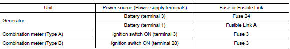
Is the inspection result normal?
YES >> GO TO 3.
NO >> Replace the blown fuse or fusible link after repairing the affected circuit.
3.CHECK GENERATOR GROUND TERMINAL CONNECTION
Check if connector F4 terminal 5 is clean.
Is the inspection result normal?
YES >> GO TO 4.
NO >> Repair connection.
4.CHECK DRIVE BELT TENSION
Check drive belt tension. Refer to EM "Inspection".
Is the inspection result normal?
YES >> Inspection End.
NO >> Repair as needed.
 Diagnosis and repair workflow
Power generation voltage variable
control system operation inspection
Diagnosis Procedure Regarding Wiring Diagram information. Refer to CHG "Wiring Diagram". CAUTION: When performing this inspection, always use a charged battery that has completed the ...
Other materials:
Maintenance under severe operating conditions
The maintenance intervals shown on the preceding pages are for normal
operating conditions. If the vehicle is mainly operated under severe driving
conditions as shown below, more frequent maintenance must be performed on the
following items as shown in the table.
Severe driving conditions
...
Timing chain
Exploded View
1. Timing chain slack guide 2. Timing chain tensioner 3. Camshaft sprocket
(EXH)
4. Camshaft sprocket (INT) 5. Plug 6. Front oil seal
7. Crankshaft pulley 8. Crankshaft pulley bolt 9. Front cover
10. Crankshaft sprocket 11. Crankshaft sprocket key 12. Oil pump sprocket
13. O ...
Categories
- Manuals Home
- Nissan Versa Owners Manual
- Nissan Versa Service Manual
- Video Guides
- Questions & Answers
- External Resources
- Latest Updates
- Most Popular
- Sitemap
- Search the site
- Privacy Policy
- Contact Us

0.0054