Nissan Versa (N17): Door switch
Component Function Check
1.CHECK FUNCTION
- Select DOOR LOCK of BCM using CONSULT.
- Select DOOR SW-DR, DOOR SW-AS, DOOR SW-RL and DOOR SW-RR in DATA MONITOR mode.
- Check that the function operates normally according to the following
conditions.
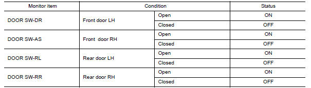
Is the inspection result normal?
YES >> Door switch is OK.
NO >> Refer to DLK "Diagnosis Procedure".
Diagnosis Procedure
Regarding Wiring Diagram information, refer to DLK "POWER DOOR LOCK SYSTEM : Wiring Diagram".
1.CHECK DOOR SWITCH INPUT SIGNAL
- Turn ignition switch OFF.
- Disconnect malfunctioning door switch connector.
- Check signal between malfunctioning door switch harness connector and
ground using oscilloscope.
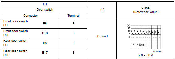
Is the inspection result normal?
YES >> GO TO 3.
NO >> GO TO 2.
2.CHECK DOOR SWITCH CIRCUIT
- Disconnect BCM connector.
- Check continuity between door switch harness connector and BCM harness
connector.
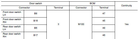
- Check continuity between door switch harness connector and ground.
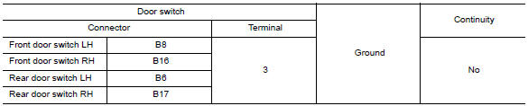
Is the inspection result normal?
YES >> Replace BCM. Refer to BCS "Removal and Installation".
NO >> Repair or replace harness.
3.CHECK DOOR SWITCH
Refer to DLK "Component Inspection".
Is the inspection result normal?
YES >> GO TO 4.
NO >> Replace malfunctioning door switch.
4.CHECK INTERMITTENT INCIDENT
Refer to GI "Intermittent Incident".
>> Inspection End.
Component Inspection
1.CHECK DOOR SWITCH
- Turn ignition switch OFF.
- Disconnect malfunctioning door switch connector.
- Check continuity between door switch terminals.
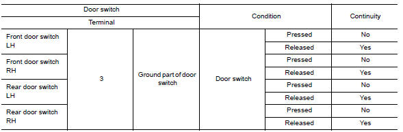
Is the inspection result normal?
YES >> Inspection End.
NO >> Replace malfunction door switch.
 Door request switch
Hazard function
Component Function Check 1.CHECK FUNCTION Select INTELLIGENT KEY of BCM using CONSULT. Select FLASHER in ACTIVE TEST mode. Touch LH or RH to check that it works normally. Is the inspecti ...
Other materials:
Steering wheel
Tilt operation
Push the lock lever 1 down and adjust the
steering wheel up or down 2 to the desired
position.
Pull the lock lever 1 up to lock the steering
wheel in place.
WARNING
Do not adjust the steering wheel while
driving. You could lose control of your
vehicle and cause an accid ...
Idle air volume learning
Description
Idle Air Volume Learning is a function of ECM to learn the idle air volume
that keeps each engine idle speed
within the specific range. It must be performed under any of the following
conditions:
Each time electric throttle control actuator or ECM is replaced.
Idle speed or ...
Categories
- Manuals Home
- Nissan Versa Owners Manual
- Nissan Versa Service Manual
- Video Guides
- Questions & Answers
- External Resources
- Latest Updates
- Most Popular
- Sitemap
- Search the site
- Privacy Policy
- Contact Us

0.0057