Nissan Versa (N17): P0112, P0113 IAT sensor
DTC Logic
DTC DETECTION LOGIC
| DTC No. | Trouble diagnosis name | DTC detecting condition | Possible cause |
| P0112 | Intake air temperature sensor circuit low input | An excessively low voltage from the sensor is sent to ECM. |
|
| P0113 | Intake air temperature sensor circuit high input | An excessively high voltage from the sensor is sent to ECM. |
DTC CONFIRMATION PROCEDURE
1.PRECONDITIONING
If DTC Confirmation Procedure has been previously conducted, always perform the following procedure before conducting the next test.
- Turn ignition switch OFF and wait at least 10 seconds.
- Turn ignition switch ON.
- Turn ignition switch OFF and wait at least 10 seconds.
>> GO TO 2.
2.PERFORM DTC CONFIRMATION PROCEDURE
- Turn ignition switch ON and wait at least 5 seconds.
- Check 1st trip DTC.
Is 1st trip DTC detected?
YES >> Go to EC, "Diagnosis Procedure".
NO >> INSPECTION END
Diagnosis Procedure
1.CHECK GROUND CONNECTION
- Turn ignition switch OFF.
- Check ground connection E. Refer to Ground Inspection in G, "Circuit Inspection".
Is the inspection result normal?
YES >> GO TO 2.
NO >> Repair or replace ground connection.
2.CHECK INTAKE AIR TEMPERATURE SENSOR POWER SUPPLY CIRCUIT
- Disconnect mass air flow (MAF) sensor (with intake air temperature sensor) harness connector.
- Turn ignition switch ON.
- Check the voltage between mass air flow sensor harness connector and ground.
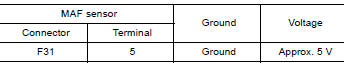
Is the inspection result normal?
YES >> GO TO 3.
NO >> Repair open circuit or short to ground or short to power in harness or connectors.
3.CHECK INTAKE AIR TEMPERATURE SENSOR GROUND CIRCUIT FOR OPEN AND SHORT
- Turn ignition switch OFF.
- Disconnect ECM harness connector.
- Check the continuity between mass air flow sensor harness connector and ECM harness connector.
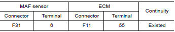
4. Also check harness for short to ground and short to power.
Is the inspection result normal?
YES >> GO TO 4.
NO >> Repair open circuit or short to ground or short to power in harness or connectors.
4.CHECK INTAKE AIR TEMPERATURE SENSOR
Refer to EC, "Component Inspection".
Is the inspection result normal?
YES >> GO TO 5.
NO >> Replace mass air flow sensor (with intake air temperature sensor). Refer to EM, "Removal and Installation".
5.CHECK INTERMITTENT INCIDENT
Refer to GI, "Intermittent Incident".
>> INSPECTION END
Component Inspection
1.CHECK INTAKE AIR TEMPERATURE SENSOR
- Turn ignition switch OFF.
- Disconnect mass air flow sensor harness connector.
- Check resistance between mass air flow sensor terminals as per the following.
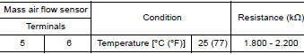
Is the inspection result normal?
YES >> INSPECTION END
NO >> Replace mass air flow sensor (with intake air temperature sensor). Refer to EM, "Removal and Installation".
 P0111 IAT sensor
Other materials:
Positive crankcase ventilation
Inspection
1.CHECK PCV VALVE
With engine running at idle, remove PCV valve from rocker cover. A
properly working valve makes a hissing noise as air passes through
it. A strong vacuum should be felt immediately when a finger is
placed over valve inlet.
Is the inspection result normal?
YES &g ...
Headlamp (LO) circuit
Description
The IPDM E/R (intelligent power distribution module engine room) controls the
headlamp low relay based on
inputs from the BCM via the CAN communication lines. When the headlamp low relay
is energized, power
flows through fuses 40 and 41, located in the IPDM E/R.
(Without dayti ...
Categories
- Manuals Home
- Nissan Versa Owners Manual
- Nissan Versa Service Manual
- Video Guides
- Questions & Answers
- External Resources
- Latest Updates
- Most Popular
- Sitemap
- Search the site
- Privacy Policy
- Contact Us

0.0075