Nissan Versa (N17): Diagnosis system (IPDM E/R) (without intelligent key system)
Diagnosis Description
AUTO ACTIVE TEST
Description
In auto active test, the IPDM E/R sends a drive signal to the following systems to check their operation.
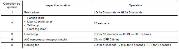
- Front wiper (LO, HI)
- Parking lamp
- License plate lamp
- Tail lamp
- Front fog lamp
- Headlamp (LO, HI)
- A/C compressor (magnet clutch)
- Cooling fan
Operation Procedure
NOTE: Never perform auto active test in the following conditions.
- Passenger door is open
- CONSULT is connected
1. Close the hood and lift the wiper arms from the windshield. (Prevent windshield damage due to wiper operation)
NOTE: When auto active test is performed with hood opened, sprinkle water on windshield beforehand.
2. Turn the ignition switch OFF.
3. Turn the ignition switch ON, and within 20 seconds, press the driver door switch 10 times. Then turn the ignition switch OFF.
4. Turn the ignition switch ON within 10 seconds. After that the horn sounds once and the auto active test starts.
5. After a series of the following operations is repeated 3 times, auto active test is completed.
NOTE:
- When auto active test has to be cancelled halfway through test, turn the ignition switch OFF.
- When auto active test is not activated, door switch may be the cause. Check door switch. Refer to DLK "Component Function Check".
Inspection in Auto Active Test
When auto active test is actuated, the following operation sequence is repeated 3 times.
Concept of Auto Active Test
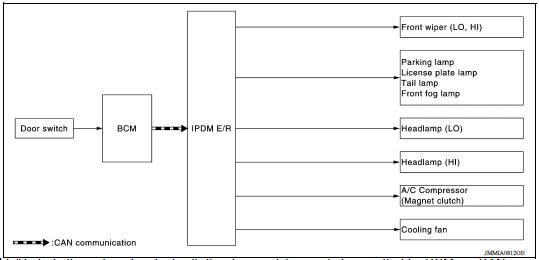
- IPDM E/R starts the auto active test with the door switch signals
transmitted by BCM via CAN communication.
Therefore, the CAN communication line between IPDM E/R and BCM is considered normal if the auto active test starts successfully.
- The auto active test facilitates troubleshooting if any systems controlled by IPDM E/R cannot be operated.
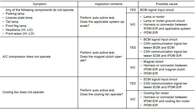
Diagnosis Chart in Auto Active Test
Consult Function (IPDM E/R)
APPLICATION ITEM
CONSULT performs the following functions via CAN communication with IPDM E/R.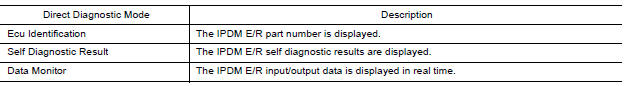

ECU IDENTIFICATION
The IPDM E/R part number is displayed.
SELF DIAGNOSTIC RESULT
Refer to PCS "DTC Index".
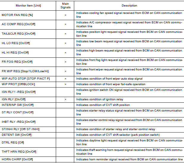
DATA MONITOR
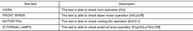
ACTIVE TEST
CAN DIAG SUPPORT MNTR
Refer to LAN "CAN Diagnostic Support Monitor".
ECU DIAGNOSIS INFORMATION
BCM, IPDM E/R
List of ECU Reference
WITH INTELLIGENT KEY
| ECU | Reference |
| BCM | BCS "Reference Value" |
| BCS "Fail-safe" | |
| BCS "DTC Inspection Priority Chart" | |
| BCS "DTC Index" | |
| IPDM E/R | PCS "Reference Value" |
| PCS "Fail-safe" | |
| PCS "DTC Index" |
WITHOUT INTELLIGENT KEY
| ECU | Reference |
| BCM | BCS "Reference Value" |
| BCS "Fail-safe" | |
| BCS "DTC Inspection Priority Chart" | |
| BCS "DTC Index" | |
| IPDM E/R | PCS "Reference Value" |
| PCS "Fail-Safe" | |
| PCS "DTC Index" |
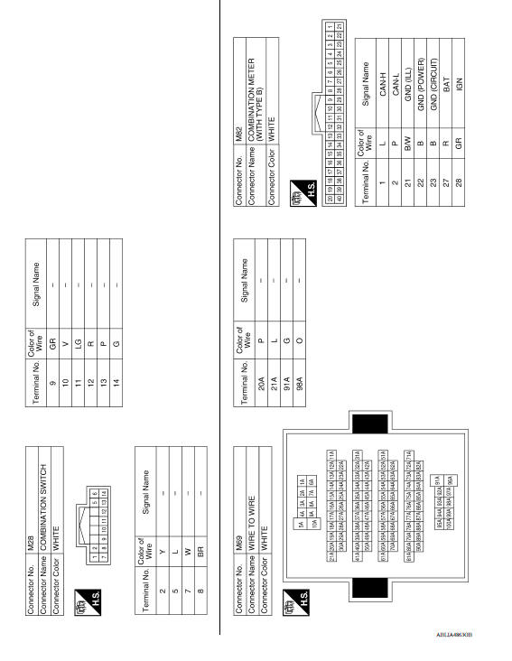
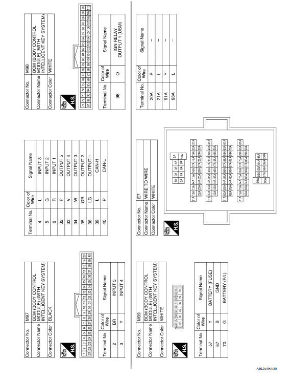
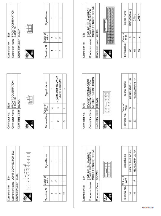
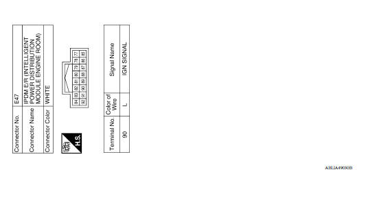
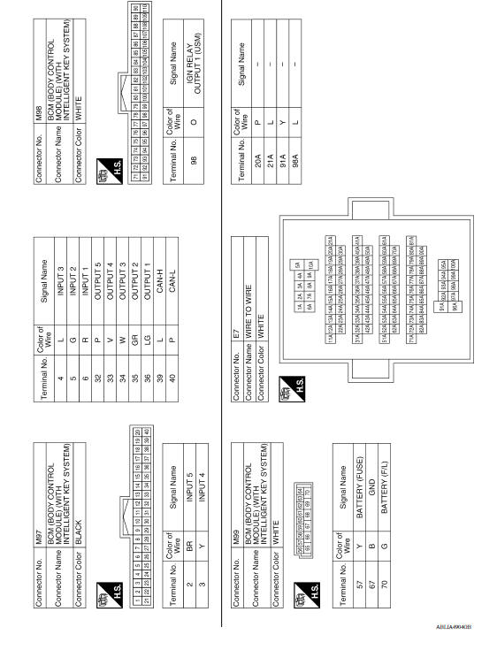
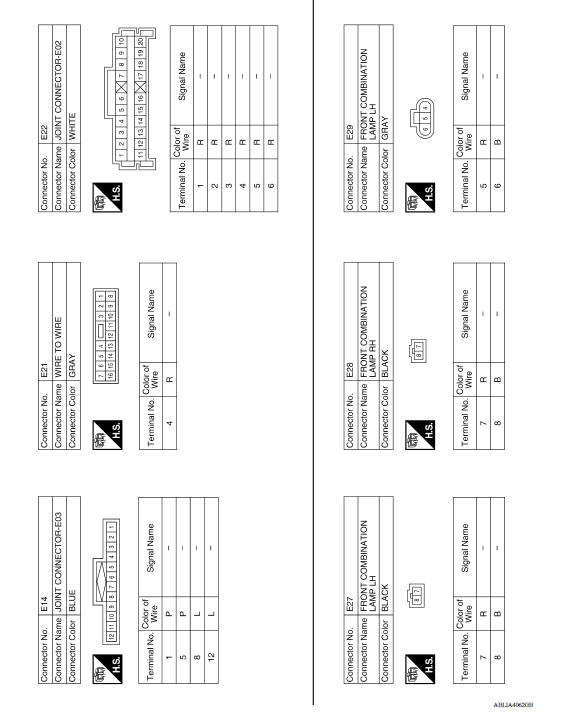
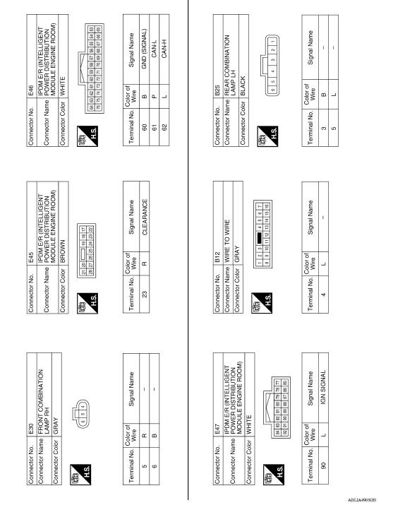
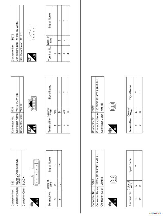
WIRING DIAGRAM
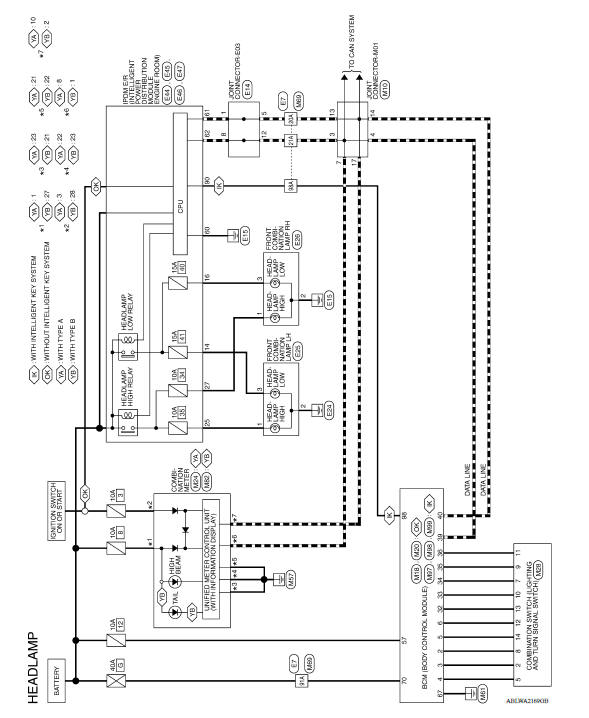
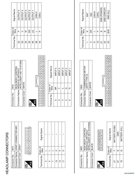
HEADLAMP
Wiring Diagram
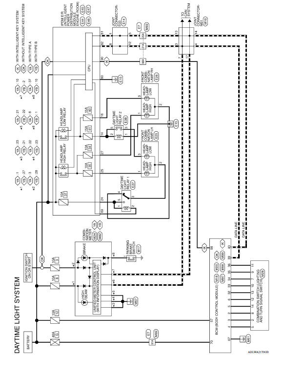
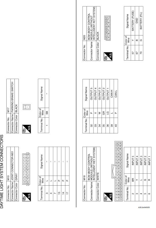
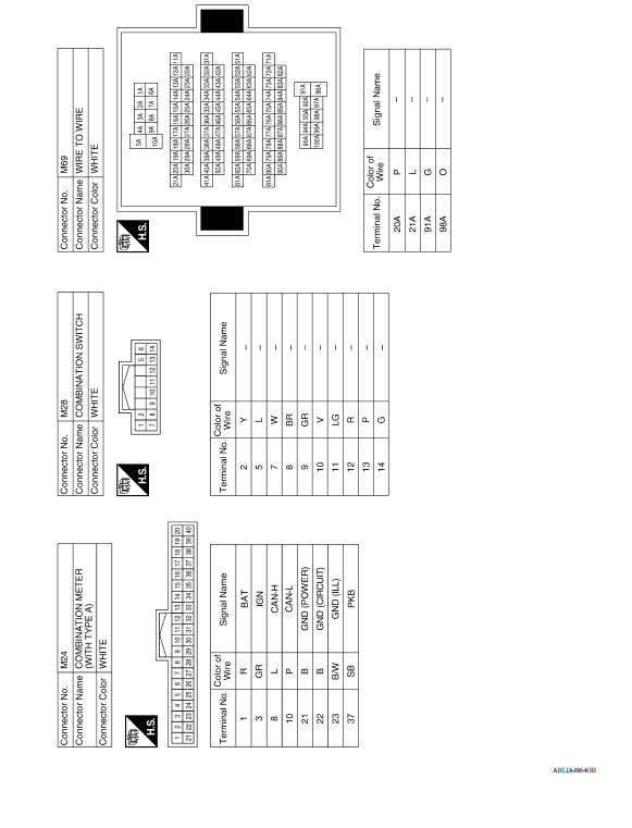
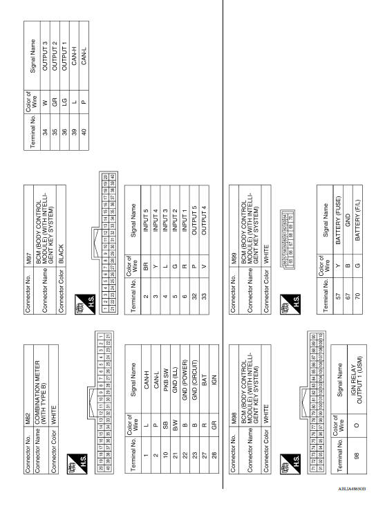
DAYTIME LIGHT SYSTEM
Wiring Diagram
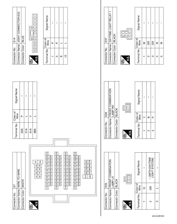
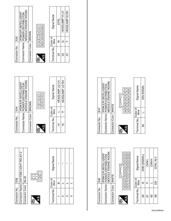
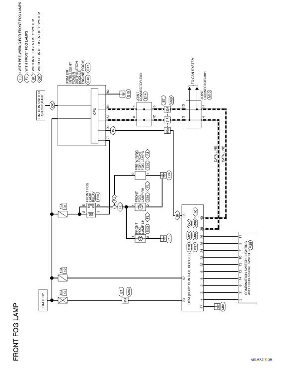
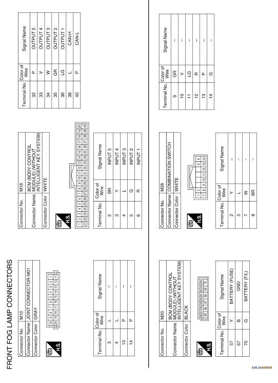
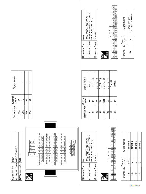
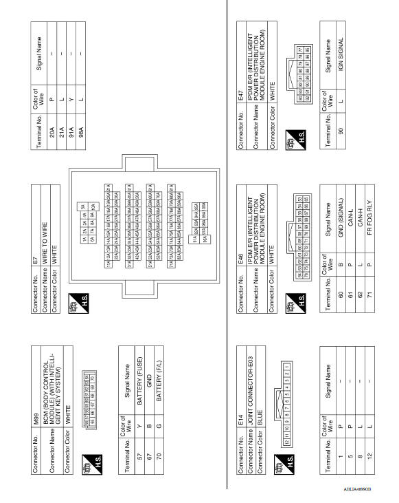
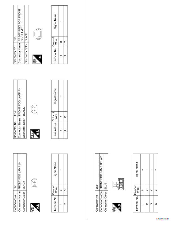
FRONT FOG LAMP
Wiring Diagram
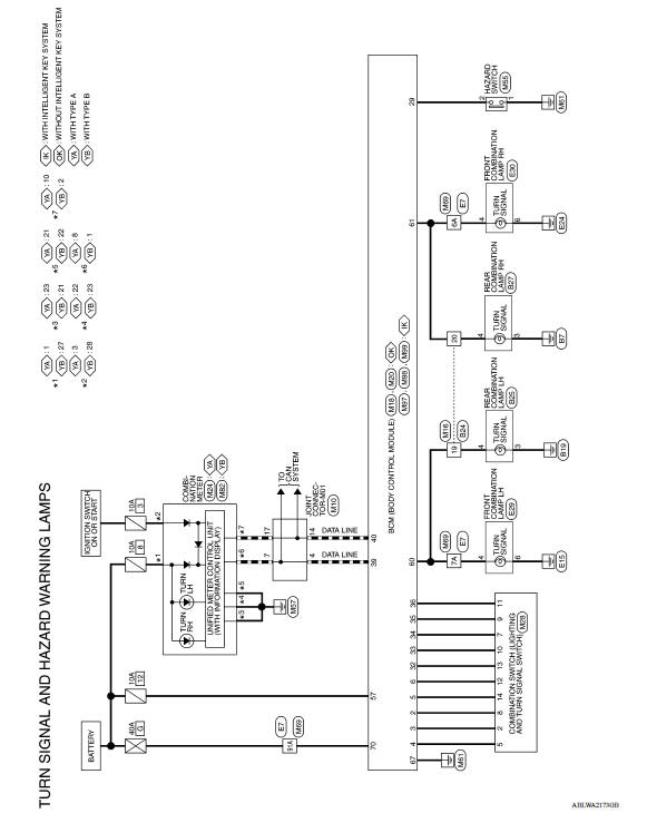
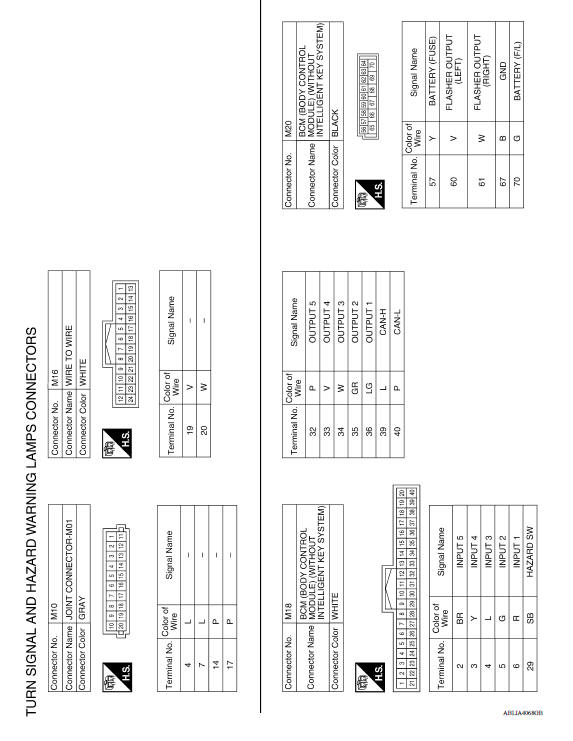
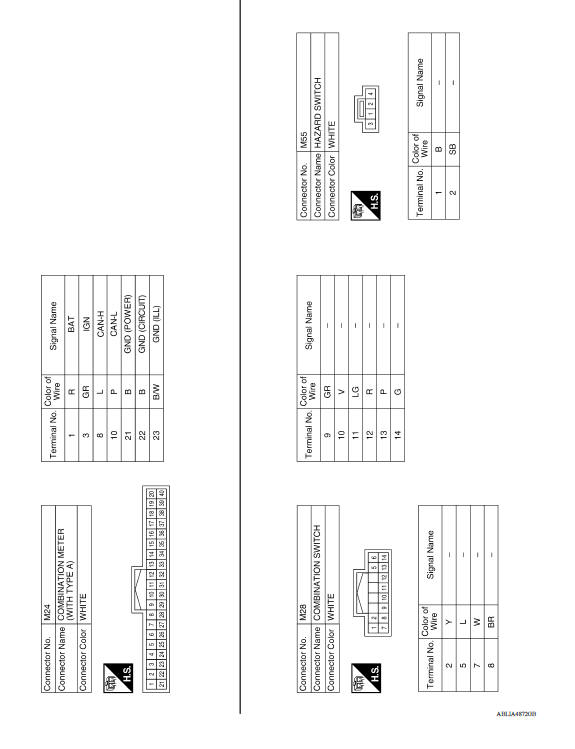
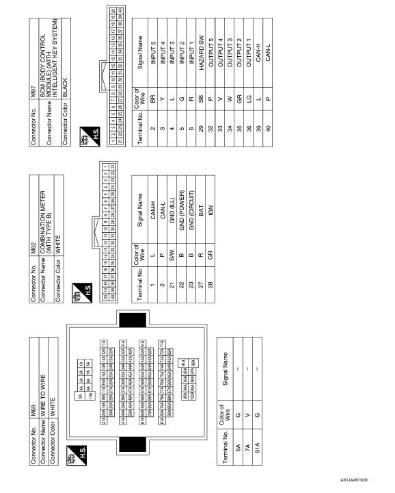
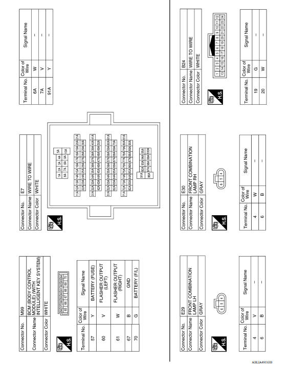
TURN SIGNAL AND HAZARD WARNING LAMP SYSTEM
Wiring Diagram
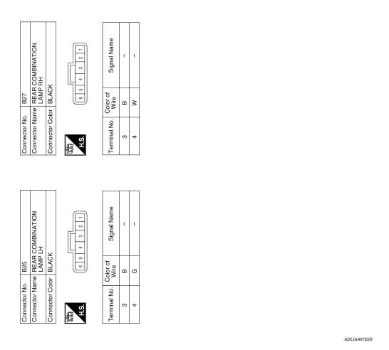
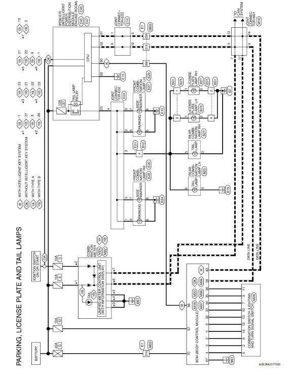
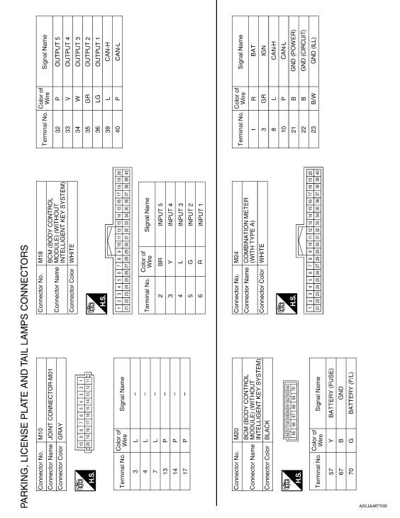
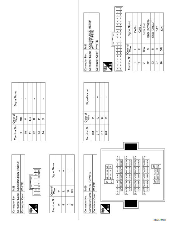
PARKING, LICENSE PLATE AND TAIL LAMPS SYSTEM
Wiring Diagram
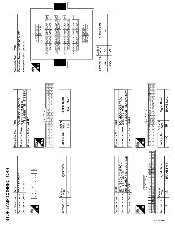
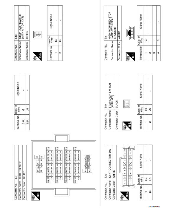
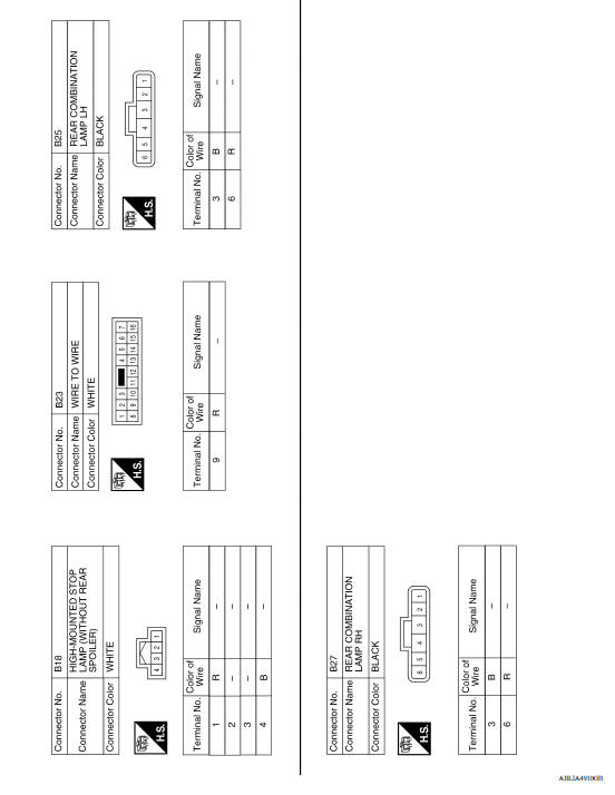
STOP LAMP
Wiring Diagram
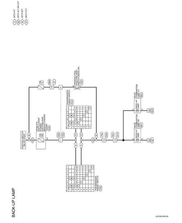
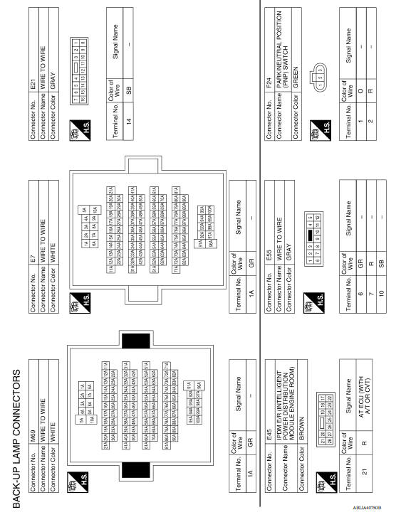
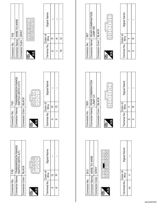
BACK-UP LAMP
Wiring Diagram
BASIC INSPECTION
 Diagnosis system (IPDM E/R) (with intelligent
key system)
Diagnosis system (IPDM E/R) (with intelligent
key system)Diagnosis and repair workflow
Work Flow OVERALL SEQUENCE DETAILED FLOW 1.INTERVIEW FOR MALFUNCTION Find out what the customer's concerns are. >> GO TO 2. 2.SYMPTOM CHECK Verify the symptom from the customer's inf ...
Other materials:
Air bags, seat belts and child restraints
1. Supplemental air bag modules
2. Roof-mounted curtain side-impact and
rollover supplemental air bag
3. Front seat-mounted side-impact
supplemental air bag
4. Front seat belt with pretensioner(s) and
shoulder height adjuster
5. Head restraints/headrests
6. Rear seat belts
7. LATCH (Low ...
OD OFF indicator lamp
Component Function Check
1.CHECK OD OFF INDICATOR LAMP FUNCTION
Check OD OFF indicator lamp turns ON for approx. 2 seconds when ignition
switch turns ON.
Is the inspection results normal?
YES >> INSPECTION END
NO >> Go to TM "Diagnosis Procedure".
Diagnosis Procedure
...
Categories
- Manuals Home
- Nissan Versa Owners Manual
- Nissan Versa Service Manual
- Video Guides
- Questions & Answers
- External Resources
- Latest Updates
- Most Popular
- Sitemap
- Search the site
- Privacy Policy
- Contact Us

0.0072