Nissan Versa (N17): Diagnosis and repair workflow
Work Flow
OVERALL SEQUENCE
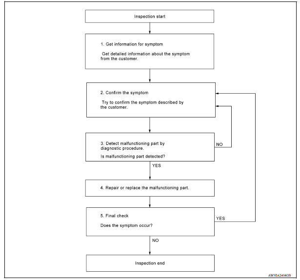
DETAILED FLOW
1.GET INFORMATION FOR SYMPTOM
Get detailed information from the customer about the symptom (the condition and the environment when the incident/malfunction occurred).
>> GO TO 2.
2.CONFIRM THE SYMPTOM
Try to confirm the symptom described by the customer. Verify relation between the symptom and the condition when the symptom is detected. Refer to AV "Symptom Table".
>> GO TO 3.
3.DETECT MALFUNCTIONING PART BY DIAGNOSTIC PROCEDURE
Inspect according to Diagnostic Procedure of the system.
Is malfunctioning part detected?
YES >> GO TO 4.
NO >> GO TO 2.
4.REPAIR OR REPLACE THE MALFUNCTIONING PART
1. Repair or replace the malfunctioning part.
2. Reconnect parts or connectors disconnected during Diagnostic Procedure.
>> GO TO 5.
5.FINAL CHECK
Refer to confirmed symptom in step 2, and make sure that the symptom is not detected.
Has the symptom been repaired?
YES >> Inspection End.
NO >> GO TO 2.
DTC/CIRCUIT DIAGNOSIS
 Diagnosis system (bluetooth control
unit)
Diagnosis system (bluetooth control
unit)
Diagnosis Description The Bluetooth control unit has two diagnostic checks. The first diagnostic check is performed automatically every ignition cycle during control unit initialization. The sec ...

Other materials:
P0720 Output speed sensor
DTC Logic
DTC DETECTION LOGIC
DTC
Trouble diagnosis name
DTC detection condition
Possible causes
P0720
Output Speed Sensor Circuit
Under the following diagnosis
conditions, the output speed
sensor value is less than 100
rpm continuously for 5 seconds
or ...
Line pressure control
LINE PRESSURE CONTROL : System Description
SYSTEM DIAGRAM
DESCRIPTION
Highly accurate line pressure control (secondary pressure control) reduces
friction for improvement of fuel
economy.
Normal Oil Pressure Control
Appropriate line pressure and secondary pressure suitable for driving
c ...
Categories
- Manuals Home
- Nissan Versa Owners Manual
- Nissan Versa Service Manual
- Video Guides
- Questions & Answers
- External Resources
- Latest Updates
- Most Popular
- Sitemap
- Search the site
- Privacy Policy
- Contact Us

0.0054