Nissan Versa (N17): B26F6 BCM
DTC Logic
DTC DETECTION LOGIC
NOTE:
- If DTC B26F6 is displayed with DTC U1000, first perform the trouble diagnosis for DTC U1000. Refer to PCS "DTC Logic".
- If DTC B26F6 is displayed with DTC U1010, first perform the trouble
diagnosis for DTC U1010. Refer to
PCS "DTC Logic".

DTC CONFIRMATION PROCEDURE
1.PERFORM DTC CONFIRMATION PROCEDURE
1. Turn ignition switch ON, and wait for 0.5 seconds or more.
2. Check "Self-diagnosis result" of BCM with CONSULT.
Is DTC detected?
YES >> Go to PCS "Diagnosis Procedure".
NO >> Inspection End.
Diagnosis Procedure
Regarding Wiring Diagram information, refer to PCS "Wiring Diagram".
1. CHECK SELF DIAGNOSTIC RESULT FOR IPDM E/R
Perform self diagnostic result for IPDM E/R.
Are any DTCs detected?
YES >> Refer to PCS"DTC Index".
NO >> GO TO 2
2. CHECK IGNITION RELAY-1 POWER SUPPLY (IPDM E/R)
Check voltage between IPDM E/R connector E47 terminal 90 and ground.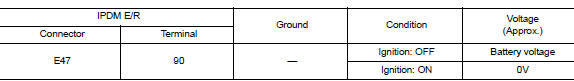
Is the inspection result normal?
YES >> Replace IPDM E/R. Refer to PCS "Removal and Installation".
NO >> GO TO 3.
3. CHECK IGNITION RELAY-1 POWER SUPPLY (BCM)
Check voltage between BCM connector M98 terminal 98 and ground.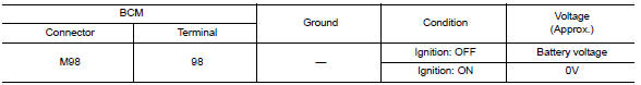
Is the inspection result normal?
YES >> Refer to GI "Intermittent Incident".
NO >> Replace BCM. Refer to BCS "Removal and Installation".
 B26F2 Ignition relay
Other materials:
Power steering
WARNING
If the engine is not running or is turned
off while driving, the power assist for
the steering will not work. Steering will
be harder to operate.
When the power steering warning light
illuminates with the engine running,
there will be no power assist for the
steering. You w ...
Maintenance precautions
When performing any inspection or maintenance
work on your vehicle, always take care to prevent
serious accidental injury to yourself or damage to
the vehicle. The following are general precautions
which should be closely observed.
WARNING
Park the vehicle on a level surface, apply
the pa ...
Categories
- Manuals Home
- Nissan Versa Owners Manual
- Nissan Versa Service Manual
- Video Guides
- Questions & Answers
- External Resources
- Latest Updates
- Most Popular
- Sitemap
- Search the site
- Privacy Policy
- Contact Us

0.0057