Nissan Versa (N17): P1554 battery current sensor
DTC Logic
DTC DETECTION LOGIC
| DTC No. | Trouble diagnosis | DTC detecting condition | Possible cause |
| P1554 | Battery current sensor performance | The output voltage of the battery current sensor is lower than the specified value while the battery voltage is high enough. |
|
DTC CONFIRMATION PROCEDURE
1.PERFORM COMPONENT FUNCTION CHECK
Perform component function check. Refer to EC, "Component Function Check".
NOTE: Use component function check to check the overall function of the battery current sensor circuit. During this check, a 1st trip DTC might not be confirmed.
Is the inspection result normal?
YES >> INSPECTION END
NO >> Go to EC, "Diagnosis Procedure".
Component Function Check
1.PRECONDITIONING
TESTING CONDITION:
- Before performing the following procedure, confirm that battery voltage is more than 12.8 V at idle.
- Before performing the following procedure, confirm that all load switches and A/C switch are turned OFF.
>> GO TO 2.
2.PERFORM COMPONENT FUNCTION CHECK
With CONSULT
- Start engine and let it idle.
- Select "BAT CUR SEN" in "DATA MONITOR" mode with CONSULT.
- Check "BAT CUR SEN" indication for 10 seconds.
"BAT CUR SEN" should be above 2,300 mV at least once.
Without CONSULT
- Start engine and let it idle.
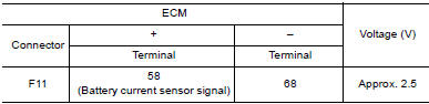
- Check the voltage between ECM harness connector terminals as per the
following.
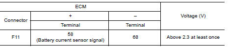
Is the inspection result normal?
YES >> INSPECTION END
NO >> Go to EC, "Diagnosis Procedure"
Diagnosis Procedure
1.CHECK GROUND CONNECTION
- Turn ignition switch OFF.
- Check ground connection E15. Refer to Ground Inspection in GI, "Circuit Inspection".
Is the inspection result normal?
YES >> GO TO 2.
NO >> Repair or replace ground connection.
2.CHECK BATTERY CURRENT SENSOR POWER SUPPLY
- Disconnect battery current sensor harness connector.
- Turn ignition switch ON.
- Check the voltage between battery current sensor harness connector and
ground.
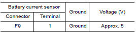
Is the inspection result normal?
YES >> GO TO 4.
NO >> GO TO 3.
3.CHECK BATTERY CURRENT SENSOR POWER SUPPLY CIRCUIT
- Turn ignition switch OFF.
- Disconnect ECM harness connector.
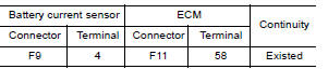
- Check the continuity between battery current sensor harness connector
and ECM harness connector.
- Also check harness for short to ground and short to power.
Is the inspection result normal?
YES >> Check intermittent incident. Refer to GI, "Intermittent Incident".
NO >> Repair or replace error-detected parts.
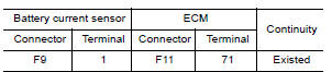
4.CHECK BATTERY CURRENT SENSOR GROUND CIRCUIT FOR OPEN AND SHORT
- Turn ignition switch OFF.
- Disconnect ECM harness connector.
- Check the continuity between battery current sensor harness connector
and ECM harness connector.
- Also check harness for short to ground and short to power.
Is the inspection result normal?
YES >> GO TO 5.
NO >> Repair or replace error-detected parts.
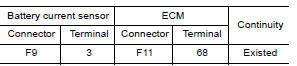
5.CHECK BATTERY CURRENT SENSOR INPUT SIGNAL CIRCUIT FOR OPEN AND SHORT
- Check the continuity between battery current sensor harness connector
and ECM harness connector.
- Also check harness for short to ground and short to power.
Is the inspection result normal?
YES >> GO TO 6.
NO >> Repair or replace error-detected parts.
6.CHECK BATTERY CURRENT SENSOR
Check battery current sensor. Refer to EC, "Component Inspection".
Is the inspection result normal?
YES >> Check intermittent incident. Refer to GI, "Intermittent Incident".
NO >> Replace battery negative cable assembly.
Component Inspection
1.CHECK BATTERY CURRENT SENSOR
- Turn ignition switch OFF.
- Reconnect harness connectors disconnected.
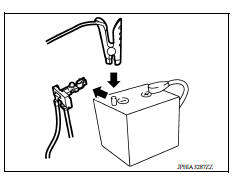
- Disconnect battery negative cable (1).
- Install jumper cable (A) between battery negative terminal and
body ground.
 : To body ground
 - Turn ignition switch ON.
- Check the voltage between ECM harness connector terminals
as per the following.
 Before measuring the
terminal voltage, confirm that the battery is fully charged. Refer to PG,
"How to Handle Battery".
Before measuring the
terminal voltage, confirm that the battery is fully charged. Refer to PG,
"How to Handle Battery".
Is the inspection result normal?
YES >> INSPECTION END
NO >> Replace battery negative cable assembly.
 P1553 battery current sensor
Other materials:
Fuel level sensor unit, fuel filter and fuel pump assembly
Exploded View
1. Lock ring 2. Fuel level sensor unit, fuel filter and
fuel pump assembly
3. O-ring
4. Fuel tank
Removal and Installation
WARNING:
Be sure to read "General Precautions" before working on the fuel system. Refer
to FL, "General Precautions".
REMOVAL
Release t ...
Spiral cable
Exploded View
1. Steering column upper cover 2. Combination switch 3. Spiral cable
4. Steering wheel 5. Driver air bag module 6. Steering lock escutcheon
7. Steering column lower cover 8. Steering column assembly
Pawl
Removal and Installation
WARNING:
Always observe the following items f ...
Categories
- Manuals Home
- Nissan Versa Owners Manual
- Nissan Versa Service Manual
- Video Guides
- Questions & Answers
- External Resources
- Latest Updates
- Most Popular
- Sitemap
- Search the site
- Privacy Policy
- Contact Us

0.0108