
Nissan Versa (N17): P2119 electric throttle control actuator
DTC Logic
DTC DETECTION LOGIC
| DTC No. | Trouble diagnosis name | DTC detecting condition | Possible cause | |
| P2119 | Electric throttle control actuator | A | Electric throttle control actuator does not function properly due to the return spring malfunction. | Electric throttle control actuator |
| B | Throttle valve opening angle in fail-safe mode is Electric throttle control actuator not in specified range. | |||
| C | ECM detect the throttle valve is stuck open. | |||
DTC CONFIRMATION PROCEDURE
1.PRECONDITIONING
If DTC Confirmation Procedure has been previously conducted, always perform the following before conducting the next test.
- Turn ignition switch OFF and wait at least 10 seconds.
- Turn ignition switch ON.
- Turn ignition switch OFF and wait at least 10 seconds.
>> GO TO 2.
2.PERFORM DTC CONFIRMATION PROCEDURE FOR MALFUNCTION A AND B
- Turn ignition switch ON and wait at least 1 second.
- Set selector lever to D (A/T or CVT) or 1st (M/T) position and wait at least 3 seconds.
- Set selector lever to P (A/T or CVT) or Neutral (M/T) position.
- Turn ignition switch OFF and wait at least 10 seconds.
- Turn ignition switch ON and wait at least 1 second.
- Set selector lever to D (A/T or CVT) or 1st (M/T) position and wait at least 3 seconds.
- Set selector lever to P (A/T or CVT) or Neutral (M/T) position.
- Turn ignition switch OFF, wait at least 10 seconds and then turn ON.
- Check DTC.
Is DTC detected?
YES >> Go to EC, "Diagnosis Procedure".
NO >> GO TO 3.
3.PERFORM DTC CONFIRMATION PROCEDURE FOR MALFUNCTION C
- Turn ignition switch ON and wait at least 1 second.
- Set selector lever to D (A/T or CVT) or 1st (M/T) position and wait at least 3 seconds.
- Set selector lever to P (A/T or CVT) or Neutral (M/T) position.
- Start engine and let it idle for 3 seconds.
- Check DTC.
Is DTC detected?
YES >> Go to EC, "Diagnosis Procedure".
NO >> INSPECTION END
Diagnosis Procedure
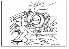
1.CHECK ELECTRIC THROTTLE CONTROL ACTUATOR VISUALLY
- Turn ignition switch OFF.
- Remove the intake air duCheck if foreign matter is caught between the throttle valve (1)
- Check if foreign matter is caught between the throttle valve (1) and the housing.
-
 : Vehicle front
Is the inspection result normal?
YES >> GO TO 2.
NO >> Remove the foreign matter and clean the electric throttle control actuator inside, and then perform throttle valve closed position learning. Refer to EC, "Work Procedure".ct. Refer to EM, "Removal and Installation".
2.REPLACE ELECTRIC THROTTLE CONTROL ACTUATOR
Replace electric throttle control actuator. Refer to EM, "Removal and Installation".
>> INSPECTION END
 P2118 throttle control motor

Other materials:
Cylinder block
Exploded View
1. Crankshaft position sensor cover 2. Crankshaft position sensor (POS) 3.
Oring
4. Drain plug 5. Cylinder block 6. Oil level gauge
7. Oil level gauge guide 8. Oring 9. Knock sensor 10. Oil temperature sensor
11. Oil pressure sensor 12. Oil jet
13. Top ring 14. Second ring ...
S connector circuit
Description
The starter motor magnetic switch is supplied with power when the ignition
switch is turned to the START position
while the selector lever is in the P (Park) or N (Neutral) position.
Diagnosis Procedure
Regarding Wiring Diagram information, refer to STR, "Wiring Diagram - Wit ...
Categories
- Manuals Home
- Nissan Versa Owners Manual
- Nissan Versa Service Manual
- Video Guides
- Questions & Answers
- External Resources
- Latest Updates
- Most Popular
- Sitemap
- Search the site
- Privacy Policy
- Contact Us

0.0121