Nissan Versa (N17): Fluid cooler & fluid warmer system
FLUID COOLER & FLUID WARMER SYSTEM : System Description
CVT FLUID COOLER SCHEMATIC

COMPONENT DESCRIPTION
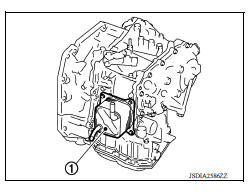
CVT Oil Warmer
- The CVT oil warmer (1) is installed on the front part of transaxle assembly.
- When engine is started while engine and CVT are cold, engine
coolant temperature rises more quickly than CVT fluid temperature.
CVT oil warmer is provided with two circuits for CVT and engine coolant respectively so that warmed engine coolant warms CVT quickly. This helps shorten CVT warming up time, improving fuel economy.
- A cooling effect is obtained when CVT fluid temperature is high.
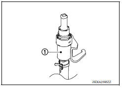
Heater Thermostat
- The heater thermostat (1) is installed on the front part of transaxle assembly.
- The heater thermostat starts opening before the completion of an engine warm-up and fully opens at the completion of the engine warm-up. This allows the transaxle to be warmed up when CVT fluid temperature is lower than coolant temperature under low temperature conditions.
SHIFT LOCK SYSTEM
SHIFT LOCK SYSTEM : System Description
The selector lever cannot be shifted from "P" position to any other position unless the ignition switch is in the ON position and the brake pedal is depressed.
KEY LOCK SYSTEM
KEY LOCK SYSTEM : System Description
- The key lock mechanism also operates as a shift lock:
With the ignition switch turned to ON, selector lever cannot be shifted from
"P" position to any other position
unless brake pedal is depressed.
With the key removed, selector lever cannot be shifted from "P" position to any other position.
The key cannot be removed unless selector lever is placed in "P" position.
- The shift lock and key lock mechanisms are controlled by the ON-OFF operation of the shift lock solenoid and by the operation of the rotator and slider located inside key cylinder, respectively.
 Structure and operation
TRANSAXLE TRANSAXLE : Cross-Sectional View 1. Converter housing 2. Oil pump 3. Counter drive gear 4. Control valve 5. Oil pan 6. Primary pulley 7. Steel belt 8. Secondary pulley 9. Planeta ...

Other materials:
Fuel injector and fuel tube
Exploded View
1. Stud bolt 2. Oring (green) 3. Fuel injector (front) 4. Clip 5. Fuel
injector (rear) 6. Oring (black) 7. Fuel tube protector 8. Fuel tube 9. Clamp
10. Quick connector cap (engine side) 11. Fuel feed hose 12. Quick connector cap
(floor pipingside) 13. Fuel connector protect ...
Preparation
Special Service Tools
The actual shapes of KentMoore tools may differ from those of special
service tools illustrated here.
Tool number
(KentMoore No.)
Tool name
Description
ST25051001
(J256951)
Oil pressure gauge &nbs ...
Categories
- Manuals Home
- Nissan Versa Owners Manual
- Nissan Versa Service Manual
- Video Guides
- Questions & Answers
- External Resources
- Latest Updates
- Most Popular
- Sitemap
- Search the site
- Privacy Policy
- Contact Us

0.0048