Nissan Versa (N17): Front bumper
Exploded View
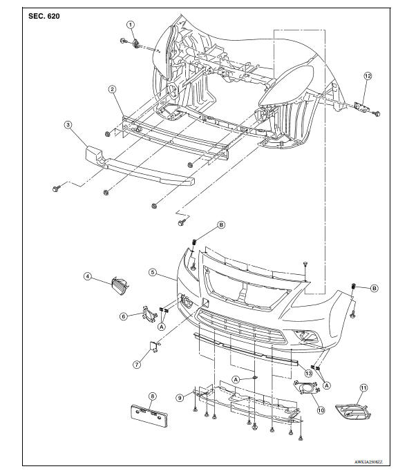
1. Front bumper side bracket (RH) 2. Front bumper reinforcement 3. Front
bumper energy absorber
4. Front bumper fascia finisher (RH)
(If equipped)
5. Front bumper fascia 6. Fog lamp finisher (RH) (if
equipped)
7. Tow cover 8. License plate bracket 9. Under cover 10. Fog lamp finisher (LH)
(if
equipped)
11. Front bumper fascia finisher (LH)
(if equipped)
12. Front bumper side bracket (LH)
13. Front spoiler A. Spring nut B. Screw grommet
 Pawl
Pawl
Removal and Installation
REMOVAL
CAUTION: Bumper fascia is made of resin. Do not apply strong force to it, and be careful to prevent contact with oil.
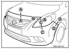
1. Open hood.
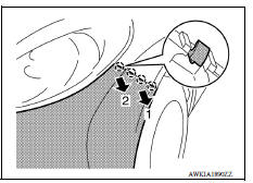
2. Remove front bumper fascia upper side clips (A).
3. Remove under cover. Refer to EXT "Removal and Installation".
4. Remove fender protector clips and screws to access bumper fascia screw. Refer to EXT "Removal and Installation".
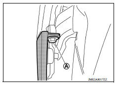
5. Remove front bumper fascia screws (A) (LH/RH).
6. Remove front bumper fascia lower side clips and screws.
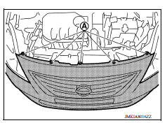
7. Pull front bumper fascia away as shown by the arrows in the illustration and then disengage front bumper fascia from front bumper side brackets (LH/RH).
 : Pawl
CAUTION: When removing front bumper fascia, two people are required to avoid damaging.
8. Disconnect the harness connectors from the front fog lamps (LH/RH) (If equipped).
9. Remove front bumper fascia.
10. Remove the following parts after removing front bumper fascia.
- Front bumper side brackets (LH/RH)
- Fog lamp finishers (LH/RH) (If equipped)
- Fog lamps (LH/RH) (If equipped). Refer to EXL "Removal and Installation".
- Front grille. Refer to EXT "Removal and Installation".
- License plate bracket
11. Remove front bumper energy absorber.
12. Remove nuts and front bumper reinforcement.
INSTALLATION
Installation is in the reverse order of removal.
NOTE:
- The following table shows the specified values for checking normal installation specifications.
- Fitting adjustment cannot be performed.
 Squeak and rattle trouble diagnoses
Under cover
Exploded View 1. Front bumper side bracket (RH) 2. Front bumper reinforcement 3. Front bumper energy absorber 4. Front bumper fascia finisher (RH) (If equipped) 5. Front bumper fascia 6. F ...
Other materials:
Intake valve timing control
Intake valve timing control : System Diagram
Intake valve timing control : system description
INPUT/OUTPUT SIGNAL CHART
Sensor
Input signal to ECM
ECM function
Actuator
Crankshaft position sensor (POS)
Engine speed*1
Piston position
Intake valve timing
con ...
Door hinge
DOOR HINGE : Removal and Installation
REMOVAL
CAUTION:
Use two people when removing or installing front door due to its
heavy weight
When removing and installing front door assembly, support the door
using a suitable tool.
Use shops cloths to protect surrounding components from dam ...
Categories
- Manuals Home
- Nissan Versa Owners Manual
- Nissan Versa Service Manual
- Video Guides
- Questions & Answers
- External Resources
- Latest Updates
- Most Popular
- Sitemap
- Search the site
- Privacy Policy
- Contact Us

0.0055