Nissan Versa (N17): Power supply and ground circuit
BCM (Body control system) (with intelligent key system)
BCM (BODY CONTROL SYSTEM) (WITH INTELLIGENT KEY SYSTEM) : Diagnosis Procedure
1.CHECK FUSES AND FUSIBLE LINK
Check that the following fuses and fusible link are not blown.
Is the fuse blown?
YES >> Replace the blown fuse or fusible link after repairing the affected circuit.
NO >> GO TO 2.
2.CHECK POWER SUPPLY CIRCUIT
1. Disconnect BCM connector M99.
2. Check voltage between BCM connector M99 and ground.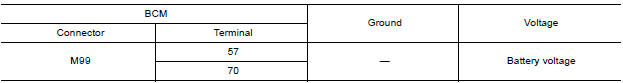
Is the inspection result normal?
YES >> GO TO 3.
NO >> Repair harness or connector.
3.CHECK GROUND CIRCUIT
Check continuity between BCM connector M99 and ground.

Is the inspection result normal?
YES >> Inspection End.
NO >> Repair harness or connector.
BCM (Body control system) (without intelligent key system)
BCM (BODY CONTROL SYSTEM) (WITHOUT INTELLIGENT KEY SYSTEM) : Diagnosis Procedure
Regarding Wiring Diagram information, refer to BCS "Wiring Diagram".
1.CHECK FUSES AND FUSIBLE LINK
Check that the following fuses and fusible link are not blown.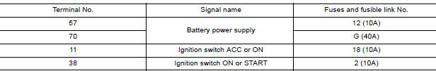
Is the fuse blown?
YES >> Replace the blown fuse or fusible link after repairing the affected circuit.
NO >> GO TO 2.
2.CHECK POWER SUPPLY CIRCUIT
1. Turn ignition switch OFF.
2. Disconnect BCM connectors.
3. Check voltage between BCM connector and ground.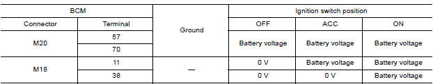
Is the inspection result normal?
YES >> GO TO 3.
NO >> Repair harness or connector.
3.CHECK GROUND CIRCUIT
Check continuity between BCM connector and ground.
Is the inspection result normal?
YES >> Inspection End.
NO >> Repair harness or connector.
IPDM E/R (With intelligent key system)
IPDM E/R (WITH INTELLIGENT KEY SYSTEM) : Diagnosis Procedure
Regarding Wiring Diagram information, refer to PCS "Wiring Diagram".
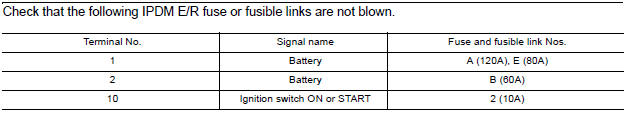
1. CHECK FUSE AND FUSIBLE LINKS
Check that the following IPDM E/R fuse or fusible links are not blown.

Is the fuse blown?
YES >> Replace the blown fuse or fusible link after repairing the affected circuit.
NO >> GO TO 2
2. CHECK BATTERY POWER SUPPLY CIRCUIT
1. Turn ignition switch OFF.
2. Disconnect IPDM E/R.
3. Check voltage between IPDM E/R connectors and ground.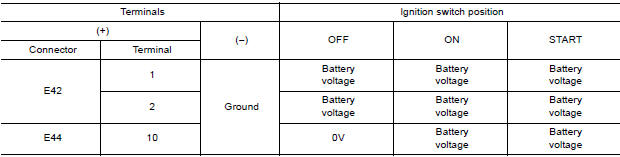
Is the measurement value normal?
YES >> GO TO 3
NO >> Repair or replace harness.
3. CHECK GROUND CIRCUIT
1. Turn ignition switch OFF.
2. Check continuity between IPDM E/R connectors and ground.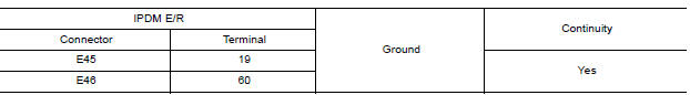
Does continuity exist?
YES >> Inspection End.
NO >> Repair or replace harness.
IPDM E/R (Without intelligent key system)
IPDM E/R (WITHOUT INTELLIGENT KEY SYSTEM) : Diagnosis Procedure
Regarding Wiring Diagram information, refer to PCS "Wiring Diagram".
1. CHECK FUSE AND FUSIBLE LINKS
Is the fuse blown?
YES >> Replace the blown fuse or fusible link after repairing the affected circuit.
NO >> GO TO 2
2. CHECK BATTERY POWER SUPPLY CIRCUIT
1. Turn ignition switch OFF.
2. Disconnect IPDM E/R.
3. Check voltage between IPDM E/R connectors and ground.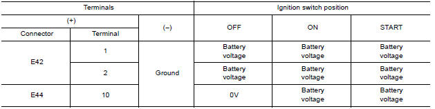
Is the measurement value normal?
YES >> GO TO 3
NO >> Repair or replace harness.
3. CHECK GROUND CIRCUIT
1. Turn ignition switch OFF.
2. Check continuity between IPDM E/R connectors and ground.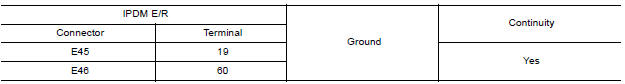
Does continuity exist?
YES >> Inspection End.
NO >> Repair or replace harness
 Diagnosis and repair workflow
Work Flow OVERALL SEQUENCE DETAILED FLOW 1.INTERVIEW FOR MALFUNCTION Find out what the customer's concerns are. >> GO TO 2. 2.SYMPTOM CHECK Verify the symptom from the customer's inf ...
Headlamp (HI) circuit
Description The IPDM E/R (intelligent power distribution module engine room) controls the headlamp high relay based on inputs from the BCM via the CAN communication lines. When the headlamp high ...
Other materials:
Seats
WARNING
Do not ride in a moving vehicle when
the seatback is reclined. This can be
dangerous. The shoulder belt will not
be against your body. In an accident,
you could be thrown into it and receive
neck or other serious injuries. You
could also slide under the lap belt and
recei ...
Idle air volume learning
Description
Idle Air Volume Learning is a function of ECM to learn the idle air volume
that keeps each engine idle speed
within the specific range. It must be performed under any of the following
conditions:
Each time electric throttle control actuator or ECM is replaced.
Idle speed or ...
Categories
- Manuals Home
- Nissan Versa Owners Manual
- Nissan Versa Service Manual
- Video Guides
- Questions & Answers
- External Resources
- Latest Updates
- Most Popular
- Sitemap
- Search the site
- Privacy Policy
- Contact Us

0.0061