
Nissan Versa (N17): Passenger air bag module
Exploded View
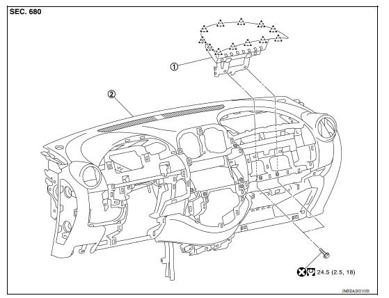
1. Passenger air bag module 2. Instrument panel assembly
 Pawl
Pawl
Removal and Installation
WARNING:
- Before servicing, turn ignition switch OFF, disconnect both the battery negative and positive terminals, then wait at least three minutes.
- Always work from the side of air bag module. Do not work in front of it.
- Do not use the air tools or electric tools for servicing.
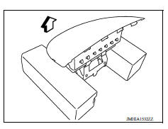
- Always place the passenger air bag module with pad side facing upward.
 : Upward
CAUTION:
- Do not insert a tool between passenger air bag module and instrument panel assembly. Doing so may cause damage.
- Do not impact the passenger air bag module.
- Replace the passenger air bag module if it has been dropped or sustained an impact.
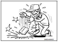
- Do not insert any foreign objects (screwdriver, etc.) into the passenger air bag module.
- Do not disassemble the passenger air bag module.
- Do not expose the passenger air bag module to temperatures exceeding 90 C (194 F).
- Do not allow oil, grease, detergent, or water to come in contact with the passenger air bag module.
REMOVAL
- Remove the glove box assembly. Refer to IP "Removal and Installation".
- Disconnect the passenger air bag module harness connector (A) from passenger air bag module.
- Remove the passenger air bag module bolts (B).
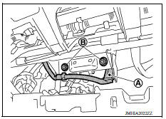
4. Disengage passenger air bag module pawls with hands.
 Pawl
Pawl
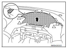
INSTALLATION
Installation is in the reverse order of removal.
CAUTION:
- Do not use the old bolts after removal, replace with the new bolts.
- Do not damage the harness while installing.
- If malfunction is detected by the air bag warning lamp, after repair or replacement of the malfunctioning parts, reset the memory using self-diagnosis or CONSULT. Refer to SRC "SRS Operation Check".
- After the work is completed, check that no system malfunction is detected by air bag warning lamp.
 Spiral cable
Exploded View 1. Steering column upper cover 2. Combination switch 3. Spiral cable 4. Steering wheel 5. Driver air bag module 6. Steering lock escutcheon 7. Steering column lower cover 8. Stee ...
Side curtain air bag module
Exploded View 1. Side curtain air bag module 2. Side curtain air bag module connector A. Adhesive tape area Removal and Installation REMOVAL CAUTION: Before servicing, turn ignition sw ...
Other materials:
Power steering
WARNING
If the engine is not running or is turned
off while driving, the power assist for
the steering will not work. Steering will
be harder to operate.
When the power steering warning light
illuminates with the engine running,
there will be no power assist for the
steering. You w ...
Exhaust valve timing control
Exhaust valve timing control : system diagram
Exhaust valve timing control : system description
INPUT/OUTPUT SIGNAL CHART
Sensor
Input signal to ECM
ECM function
Actuator
Crankshaft position sensor (POS)
Engine speed*1
Piston position
Exhaust valve timing c ...
Categories
- Manuals Home
- Nissan Versa Owners Manual
- Nissan Versa Service Manual
- Video Guides
- Questions & Answers
- External Resources
- Latest Updates
- Most Popular
- Sitemap
- Search the site
- Privacy Policy
- Contact Us

0.0064