Nissan Versa (N17): Power distribution system
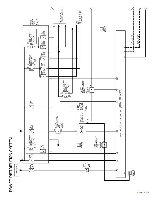
POWER DISTRIBUTION SYSTEM : System Diagram
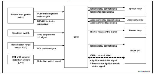
POWER DISTRIBUTION SYSTEM : System Description
SYSTEM DESCRIPTION
- PDS (POWER DISTRIBUTION SYSTEM) is the system that BCM controls with the operation of the pushbutton ignition switch and performs the power distribution to each power circuit. This system is used instead of the mechanical power supply changing mechanism with the operation of the conventional key cylinder.
- The push-button ignition switch can be operated when Intelligent Key is in the following condition.
- Intelligent Key is in the detection area of the inside key antenna.
- Intelligent Key backside is contacted to push-button ignition switch.
- The push-button ignition switch operation is input to BCM as a signal. BCM changes the power supply position according to the status and operates the following relays to supply power to each power circuit.
- Ignition relay-1
- Ignition relay-2
- Accessory relay-1
- Accessory relay-2
- Blower motor relay
NOTE: The engine switch operation changes due to the conditions of brake pedal, selector lever and vehicle speed.
- The power supply position can be confirmed with the lighting of the indicators in the push-button ignition switch.
BATTERY SAVER SYSTEM
When all the following conditions are met for 30 minutes, the battery saver system will cut off the power supply to prevent battery discharge.
- The ignition switch is in the ACC or ON position
- All doors are closed
- Selector lever is in the P (park) position
Reset Condition of Battery Saver System
In order to prevent the battery from discharging, the battery saver system will cut off the power supply when all doors are closed, the selector lever is in P (park) position and the ignition switch is left in the ACC or ON position for 30 minutes. If any of the following conditions are met the battery saver system is released and the steering will change automatically to lock position from OFF position.
- Opening any door
- Operating door request switch on door handle
- Operating Intelligent Key
POWER SUPPLY POSITION CHANGE TABLE BY PUSH-BUTTON IGNITION SWITCH OPERATION
The power supply position changing operation can be performed with the following operations.
NOTE:
- When an Intelligent Key is within the detection area of inside key antenna and when Intelligent Key backside is contacted to push-button ignition switch, it is equivalent to the operations below.
- When starting the engine, the BCM monitors under the engine start conditions:
- Brake pedal operating condition
- Selector lever position
- Vehicle speed
Vehicle speed: less than 4 km/h (2.5 MPH)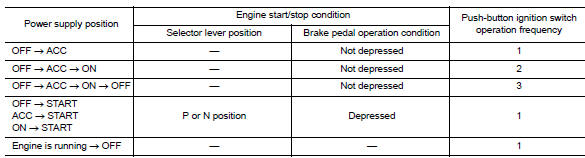
Vehicle speed: 4 km/h (2.5 MPH) or more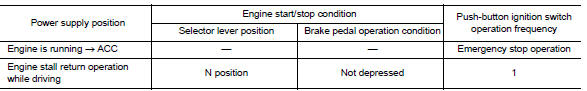
Emergency stop operation
- Press and hold the push-button ignition switch for 2 seconds or more.
- Press the push-button ignition switch 3 times or more within 1.5 seconds.
DIAGNOSIS SYSTEM (BCM)
COMMON ITEM
COMMON ITEM : CONSULT Function (BCM - COMMON ITEM)
APPLICATION ITEM
CONSULT performs the following functions via CAN communication with BCM.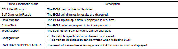
SYSTEM APPLICATION
BCM can perform the following functions.
INTELLIGENT KEY
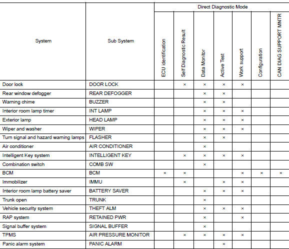
INTELLIGENT KEY : CONSULT Function (BCM - INTELLIGENT KEY)
SELF DIAGNOSTIC RESULT
Refer to BCS "DTC Index".
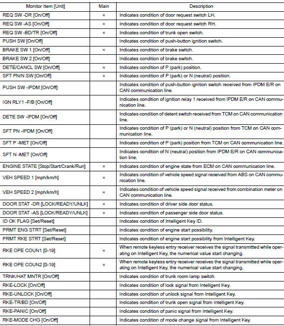
DATA MONITOR
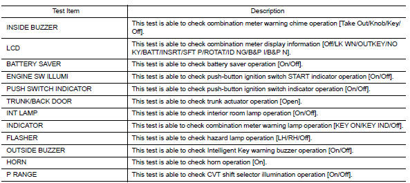
ACTIVE TEST
WORK SUPPORT
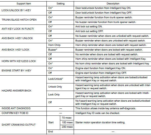
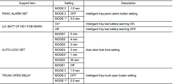
*: Initial Setting
ECU DIAGNOSIS INFORMATION
BCM
List of ECU Reference
| ECU | Reference |
| BCM | BCS "Reference Value" |
| BCS "Fail-safe" | |
| BCS "DTC Inspection Priority Chart" | |
| BCS "DTC Index" |
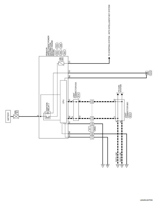
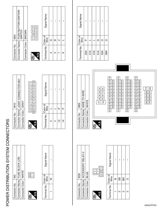
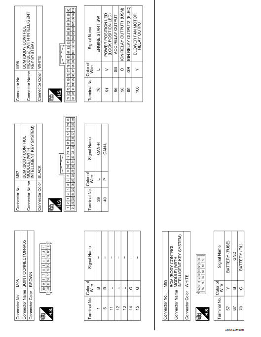
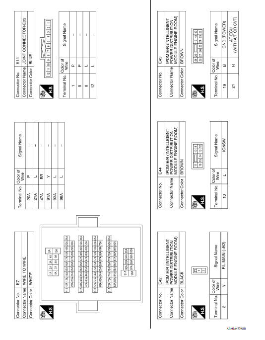
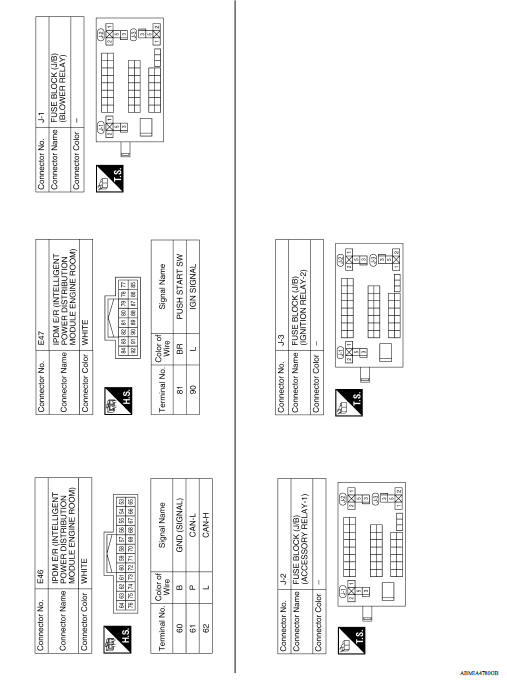
WIRING DIAGRAM
POWER DISTRIBUTION SYSTEM
Wiring Diagram
BASIC INSPECTION
 Precautions
Diagnosis and repair work flow
Work Flow OVERALL SEQUENCE DETAILED FLOW 1.GET INFORMATION FOR SYMPTOM 1. Get detailed information from the customer about the symptom (the condition and the environment when the incident/m ...
Other materials:
Doors
When the doors are locked using one of the
following methods, the doors cannot be opened
using the inside or outside door handles. The
doors must be unlocked to open the doors.
WARNING
Before opening any door, always look
for and avoid oncoming traffic.
To help avoid risk of injury or de ...
Diagnosis and repair workflow
Workflow
OVERALL SEQUENCE
DETAILED FLOW
1.INTERVIEW CUSTOMER
Interview the customer to obtain as much information as possible about the
conditions and environment under
which the malfunction occurred.
>> GO TO 2.
2.SYMPTOM CHECK
Verify symptoms.
>> GO TO 3.
3.CHECK FOR DT ...
Categories
- Manuals Home
- Nissan Versa Owners Manual
- Nissan Versa Service Manual
- Video Guides
- Questions & Answers
- External Resources
- Latest Updates
- Most Popular
- Sitemap
- Search the site
- Privacy Policy
- Contact Us

0.0047