Nissan Versa (N17): Rear power window switch
Component Function Check
1. CHECK FUNCTION
Check rear power window motor operation with rear power window switch.
Is the inspection result normal?
YES >> Inspection End.
NO >> Refer to PWC "Diagnosis Procedure".
Diagnosis Procedure
Regarding Wiring Diagram information, refer to PWC "Wiring Diagram".
1.CHECK REAR POWER WINDOW SWITCH INPUT SIGNAL
1. Turn ignition switch OFF.
2. Disconnect rear power window switch connector.
3. Turn ignition switch ON.
4. Check voltage between rear power window switch harness connector and
ground.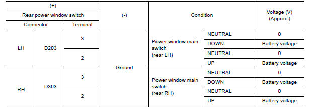 Is the Is the Is the
inspection result normal?
Is the Is the Is the
inspection result normal?
YES >> GO TO 3.
NO >> GO TO 2.
2.CHECK REAR POWER WINDOW SWITCH CIRCUIT
1. Turn ignition switch OFF.
2. Disconnect power window main switch connector.
3. Check continuity between power window main switch harness connector and
rear power window switch
harness connector.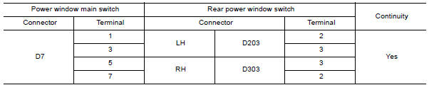
4. Check continuity between power window main switch harness connector and
ground.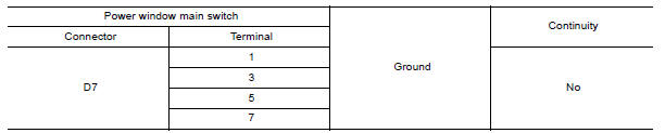
Is the inspection result normal?
YES >> Replace power window main switch. Refer to PWC "Removal and Installation".
NO >> Repair or replace harness.
3.CHECK REAR POWER WINDOW SWITCH
Check rear power window switch.
Refer to PWC "Component Inspection".
Is the inspection result normal?
YES >> Check intermittent incident. Refer to GI "Intermittent Incident".
NO >> Replace rear power window switch. Refer to PWC "Removal and Installation".
Component Inspection
1.CHECK REAR POWER WINDOW SWITCH
1. Turn ignition switch OFF.
2. Disconnect rear power window switch connector.
3. Check rear power window switch terminals under the following conditions.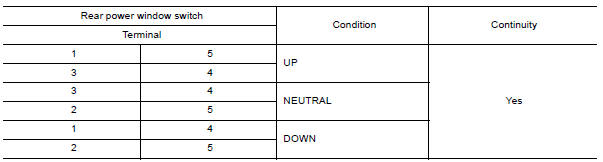
Is the inspection result normal?
YES >> Inspection End.
NO >> Replace rear power window switch. Refer to PWC "Removal and Installation".
 Front power window switch (passenger
side)
Front power window switch (passenger
side)
Component Function Check 1. CHECK FUNCTION Check front power window motor RH operation with front power window switch RH. Is the inspection result normal? YES >> Inspection End. NO >> ...

Other materials:
Air bags, seat belts and child restraints
1. Supplemental air bag modules
2. Roof-mounted curtain side-impact and
rollover supplemental air bag
3. Front seat-mounted side-impact
supplemental air bag
4. Front seat belt with pretensioner(s) and
shoulder height adjuster
5. Head restraints/headrests
6. Rear seat belts
7. LATCH (Low ...
Description
Engine Cooling System
M/T models
CVT and A/T models
Engine Cooling System Schematic
M/T models
CVT and A/T models
OVERHEATING CAUSE ANALYSIS
Troubleshooting Chart
Symptom
Check items
Cooling system
parts
malfunction
Poor heat transfer
...
Categories
- Manuals Home
- Nissan Versa Owners Manual
- Nissan Versa Service Manual
- Video Guides
- Questions & Answers
- External Resources
- Latest Updates
- Most Popular
- Sitemap
- Search the site
- Privacy Policy
- Contact Us

0.0053