Nissan Versa (N17): Road wheel
Inspection
ALUMINUM WHEEL
- Check tires for wear and improper inflation.
- Check wheels for deformation, cracks and other damage. If deformed, remove wheel and check wheel runout.
a. Remove tire from aluminum wheel and mount wheel on a balancer machine.
b. Set dial indicator as shown.
c. Check runout, if runout value exceeds the limit, replace aluminum wheel.
Limit
Lateral Deflection (A) Refer to WT "Road Wheel".
Vertical Deflection (B) Refer to WT "Road Wheel".
STEEL WHEEL
- Check tires for wear and improper inflation.
- Check wheels for deformation, cracks and other damage. If deformed, remove wheel and check wheel runout.
a. Remove tire from steel wheel and mount wheel on a balancer machine.
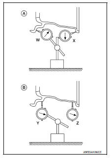
b. Set two dial indicators as shown.
c. Set each dial indicator to "0".
d. Rotate wheel and check dial indicators at several points around the circumference of the wheel.
e. Calculate runout at each point as shown below.
Lateral deflection (A) = (W+X)/2
Vertical deflection (B) = (Y+Z)/2
f. Select maximum positive runout value and the maximum negative value.
Add the two values to determine total runout.
In case a positive or negative value is not available, use the maximum value (negative or positive) for total runout.
If the total runout value exceeds the limit, replace steel wheel.
Limit
Lateral Deflection (A) Refer to WT "Road Wheel".
Vertical Deflection (B) Refer to WT "Road Wheel".
REMOVAL AND INSTALLATION
 Low tire pressure warning lamp
blinks
Low tire pressure warning lamp
blinks
Diagnosis Procedure NOTE: If low tire pressure warning lamp repeats blinking ON for 2 seconds and OFF for 0.2 seconds, wake-up operation for all transmitters is not complete. Carry out transmitt ...
Road wheel tire assembly
Adjustment BALANCING WHEELS (ADHESIVE WEIGHT TYPE) Preparation Before Adjustment Remove inner and outer balance weights from the road wheel. Using releasing agent, remove double-faced adhesive ...
Other materials:
P1715 Input speed sensor
Description
ECM receives input speed sensor signal from TCM via the CAN communication
line. ECM uses this signal for
engine control.
DTC Logic
DTC DETECTION LOGIC
NOTE:
If DTC P1715 is displayed with DTC UXXXX, first perform the
trouble diagnosis for DTC UXXXX.
If DTC P1715 is displa ...
P0717 Input speed sensor A
DTC Logic
DTC DETECTION LOGIC
DTC
Trouble diagnosis name
DTC detection condition
Possible causes
P0717
Input/Turbine Speed Sensor "A"
Circuit No Signal
Under the following diagnosis
conditions, the input speed sensor
value is less than 600 rpm
continuousl ...
Categories
- Manuals Home
- Nissan Versa Owners Manual
- Nissan Versa Service Manual
- Video Guides
- Questions & Answers
- External Resources
- Latest Updates
- Most Popular
- Sitemap
- Search the site
- Privacy Policy
- Contact Us

0.0072