Nissan Versa (N17): Transaxle
Transaxle : cross-sectional view
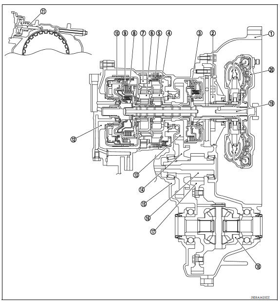
1. Converter housing 2. Oil pump 3. Low clutch 4. Rear planetary gear 5. Low & reverse brake 6. Front planetary gear 7. Low one-way clutch 8. High clutch 9. Reverse clutch 10. 2-4 brake band (Brake band) 11. Band servo piston 12. Side cover 13. Output gear 14. Idler gear 15. Transaxle case 16. Reduction pinion gear 17. Final gear 18. Differential case 19. Input shaft 20. Torque converter
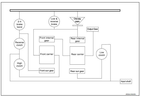
Transaxle : system diagram
Transaxle : system description
DESCRIPTION
With the use of 2 sets of planetary gears, A/T enables 4-speed transmission for forward and 1-speed transmission for backward, depending on the combination of 3 sets of multiple-disc clutches, a set of multiple-disc brakes, a set of one-way clutches and a set of brake bands.
CLUTCH/BRAKE AND BAND CHART
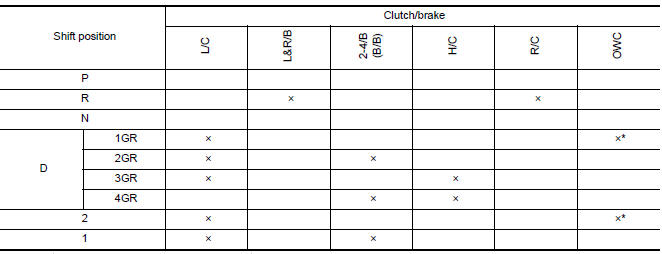
*: Operates during "progressive" acceleration.
P POSITION (PARKING MECHANISM)
When the selector lever is shifted to the "P" position, the parking pole engages with the parking gear (integrated with the idler gear), fixing the output shaft in place.
TRACTION TRANSMISSION OF EACH RANGE
"P" position, "N" position
The drive force from the input shaft is not transmitted because all clutches and bands are released.
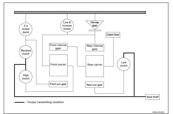
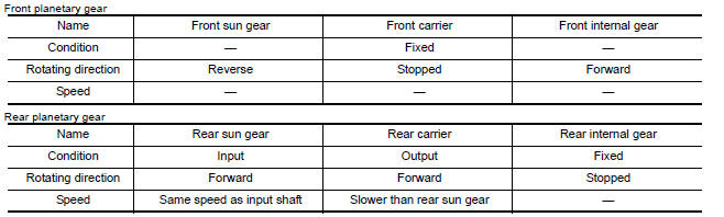
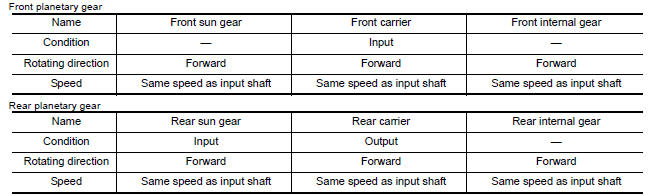
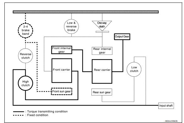
"1" position, "D1" position
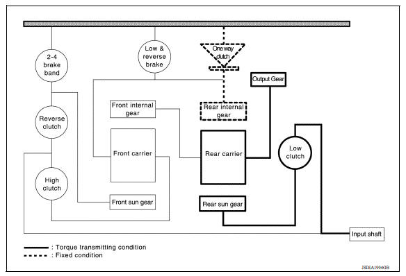
- The drive force from the input shaft is transmitted via the engaged low
clutch and turns the rear sun gear forwards.
This causes the rear internal gear to turn backwards, however it is stopped by the one-way clutch.
The rear gear turns forward and the force is transmitted to the output gear after being slowed down.
NOTE: When coasting, because the front carrier is able to turn forward, engine braking does not occur.
- The status of each planetary gear is as shown below.
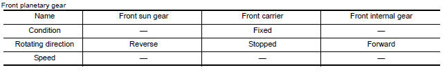
"1" position, "D1" position, engine brake
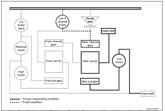
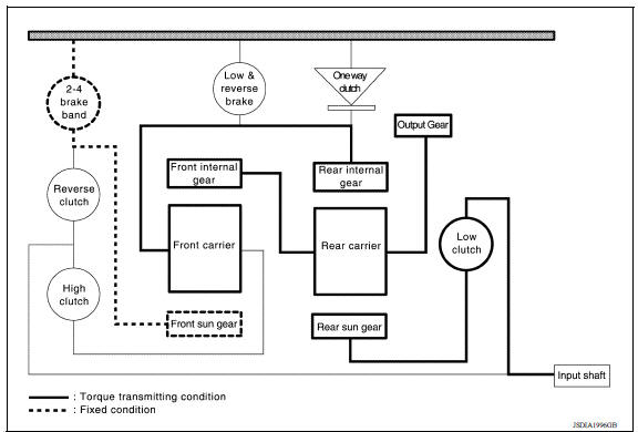
- The drive force from the input shaft is transmitted via the engaged low
clutch and turns the rear sun gear forwards.
This causes the rear internal gear to turn backwards, however it is stopped by the one-way clutch.
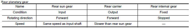
The rear carrier turns forward and the force is transmitted to the output gear after being slowed down.
- The status of each planetary gear is as shown below.
"2" position, "D2" position
- In 1st gear, the front sun gear is turning in reverse. However the 2-4 brake operates and fixes the front sun gear in place. When this happens, the front carrier turns in the forward direction. As a result, when the front internal gear transmits force to the output gear, it turns forward at a faster speed than when in 1st gear.
- Because the rear internal gear and front carrier are turning forward, the one-way clutch turns freely.
- The status of each planetary gear is as shown below.
"D3" position
- The low clutch and high clutch that are connected to the input shaft are engaged, creating a single power transmitting mechanism and rotating while engaged.
- The status of each planetary gear is as shown below.
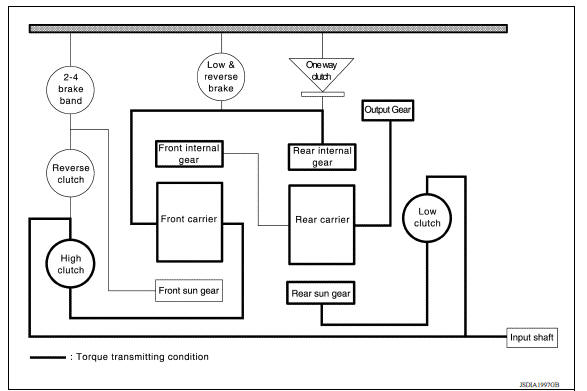
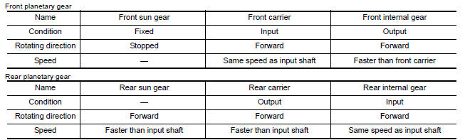
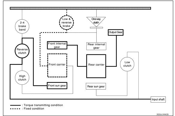
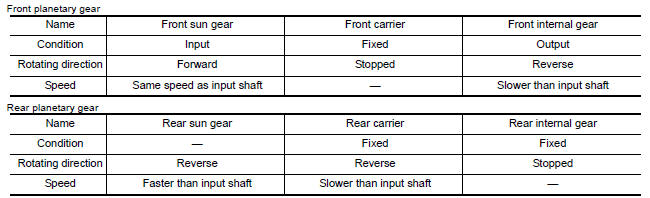
"D4" position
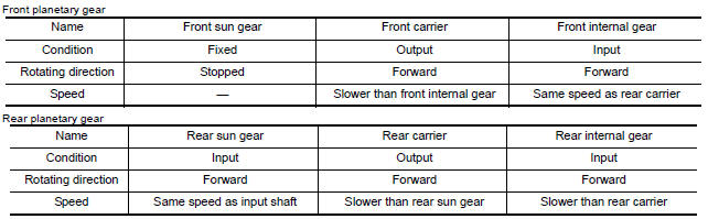
- The drive force input from the input shaft is transmitted by forward rotation of the engaged high clutch to the front carrier. Operation of the 2-4 brake fastens the front sun gear in place, causing the front carrier to turn forward. As a result, the front internal gear turns faster, the rear carrier turns forward, and force is transmitted to the output gear.
- The status of each planetary gear is as shown below.
"R" position
- The drive force from the input shaft is transmitted by forward rotation of the engaged reverse clutch to the front sun gear. Engagement of the low & reverse brake fastens the front carrier in place, causing the front internal gear to turn in reverse and transmitting force by reverse rotation to the output gear.
- The status of each planetary gear is as shown below.
Transaxle : component description
| Name (abbreviation) | FUNCTION |
| Torque converter | Amplifies the drive force from the engine and transmits it to the transmission input shaft. |
| Oil pump | Driven by the engine, this component supplies oil to the torque converter, control valve assembly, and lubricated parts. |
| 4-point gear | Transmits drive force from the transmission mechanism to the output gear, idler gear, reduction gear, and final gear. |
| Low clutch (L/C) | Connects the rear sun gear and input shaft |
| High clutch (H/C) | Connects the front carrier and input shaft |
| Reverse clutch (R/C) | Connects the front sun gear and input shaft |
| Low & reverse brake (L&R/B) | Fastens the rear internal gear and front carrier in place. |
| 2-4 brake (2-4/B) | Brake band that fastens the front sun gear in place. |
| One-way clutch (OWC) | This clutch prevents reverse turning of the front carrier and rear internal gear. It operates not hydraulically but mechanically. |
| Planetary gear | Transmits drive force to various positions by engagement and release of the clutches and bands. |
Shift lock system
Shift lock system : system description
The selector lever cannot be shifted from "P" position to any other position unless the ignition switch is in the ON position and the brake pedal is depressed.
Key lock system
Key lock system : system description
- The key lock mechanism also operates as a shift lock:
With the ignition switch turned to ON, selector lever cannot be shifted from
"P" position to any other position
unless brake pedal is depressed.
With the key removed, selector lever cannot be shifted from "P" position to any other position.
The key cannot be removed unless selector lever is placed in "P" position.
- The shift lock and key lock mechanisms are controlled by the ON-OFF operation of the shift lock solenoid and by the operation of the rotator and slider located inside key cylinder, respectively.
 A/T Shift lock system
A/T Shift lock system : component parts location 1 Stop lamp switch. 2 Shift lock release lever. 3 Park position switch. 4 Shift lock solenoid. A/T Shift lock system : component description ...
A/T control system
A/T control system : system diagram ...
Other materials:
Parking/parking on hills
WARNING
Do not stop or park the vehicle over
flammable materials such as dry grass,
waste paper or rags. They may ignite
and cause a fire.
Safe parking procedures require that
both the parking brake be set and the
transmission placed into P (Park) or in
an appropriate gear for ...
Preparation
Special Service Tools
The actual shapes of KentMoore tools may differ from those of special
service tools illustrated here.
Tool number
(KentMoore No.)
Tool name
Description
KV10111100
(J37228)
Seal cutter
Removing oil pan (lower and upper) etc.
...
Categories
- Manuals Home
- Nissan Versa Owners Manual
- Nissan Versa Service Manual
- Video Guides
- Questions & Answers
- External Resources
- Latest Updates
- Most Popular
- Sitemap
- Search the site
- Privacy Policy
- Contact Us

0.0054