Nissan Versa (N17): Warning function
WARNING FUNCTION : System Description
OPERATION DESCRIPTION
The warning function are as per the following items and are given to the user as warning information and warnings using combinations of Intelligent Key warning buzzer, combination meter buzzer, KEY warning lamp, shift P warning lamp and engine start operation indicator lamp.
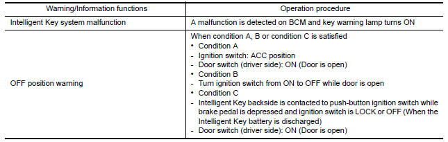
- Intelligent Key system malfunction
- OFF position warning
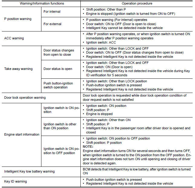
- P position warning
- ACC warning
- Take away warning
- Door lock operation warning
- Engine start information
- Intelligent Key low battery warning
- Key ID warning
OPERATION CONDITION
Operation condition of warning and information is as per the following table.
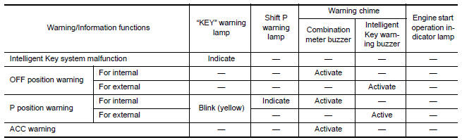
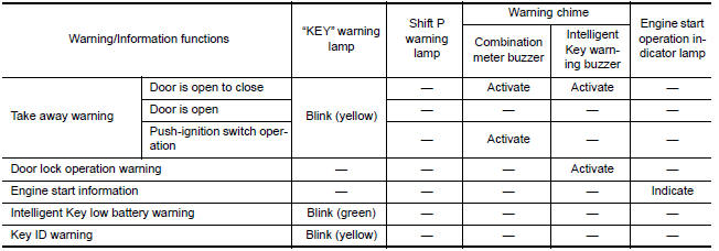
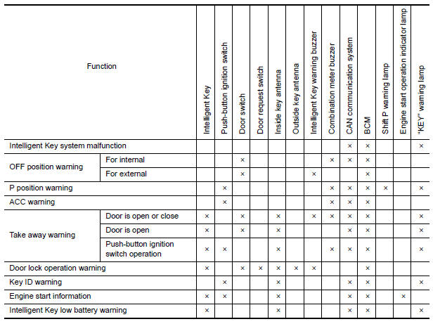
WARNING METHOD
The following table shows the alarm or warning methods with chime.
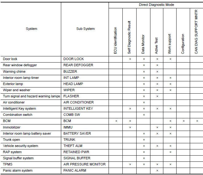
LIST OF OPERATION RELATED PARTS
Parts marked with × are the parts related to operation.
SYSTEM (TRUNK LID OPENER SYSTEM)
System Description
System Diagram
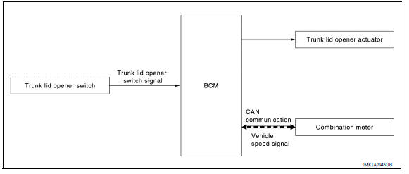
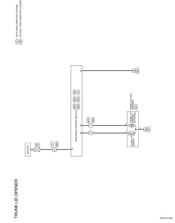
TRUNK LID OPENER OPERATION
When trunk lid opener switch is ON, BCM operates trunk lid opener actuator.
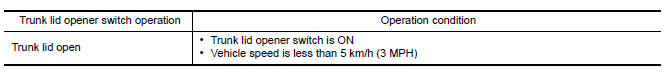
OPERATION CONDITION
If the following conditions are satisfied, trunk open operation is performed.
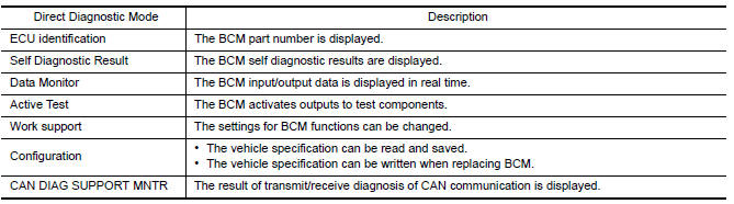
DIAGNOSIS SYSTEM (BCM)
COMMON ITEM
COMMON ITEM : CONSULT Function (BCM - COMMON ITEM)
APPLICATION ITEM
CONSULT performs the following functions via CAN communication with BCM.
SYSTEM APPLICATION
BCM can perform the following functions.
DOOR LOCK
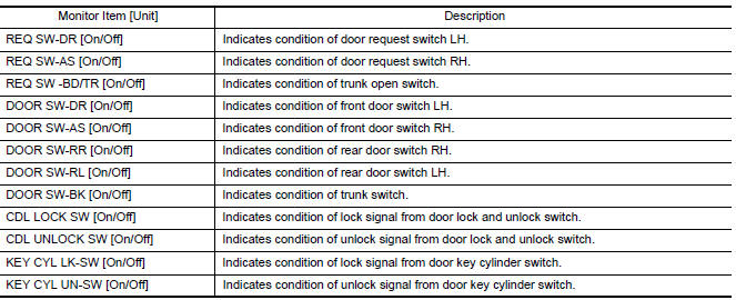
DOOR LOCK : CONSULT Function (BCM - DOOR LOCK)
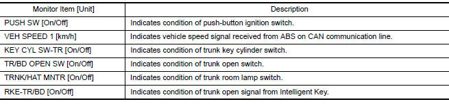
DATA MONITOR
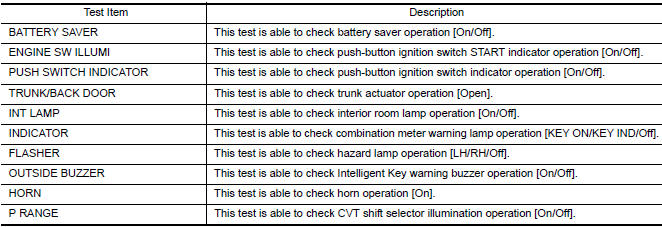
ACTIVE TEST

WORK SUPPORT
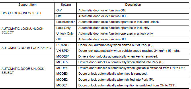
*: Initial setting
INTELLIGENT KEY
INTELLIGENT KEY : CONSULT Function (BCM - INTELLIGENT KEY)
SELF DIAGNOSTIC RESULT
Refer to BCS "DTC Index".
DATA MONITOR 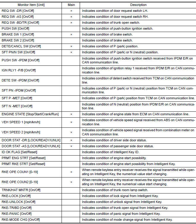
ACTIVE TEST 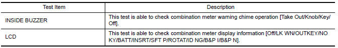
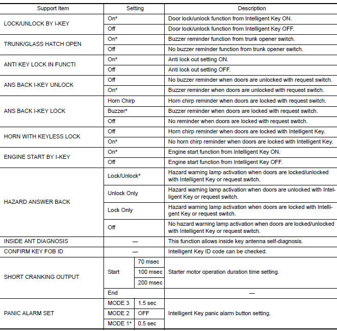
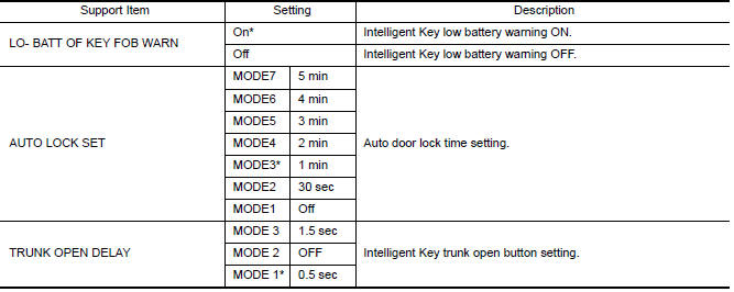
WORK SUPPORT
*: Initial Setting
TRUNK
TRUNK : CONSULT Function (BCM - TRUNK)
DATA MONITOR
ECU DIAGNOSIS INFORMATION
BCM
List of ECU Reference
|
ECU |
Reference |
| BCM | BCS "Reference Value" |
| BCS "Fail-safe" | |
| BCS "DTC Inspection Priority Chart" | |
| BCS "DTC Index" |
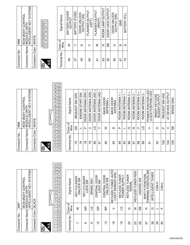
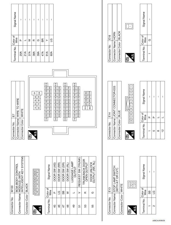
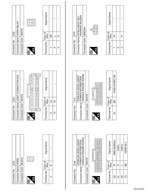
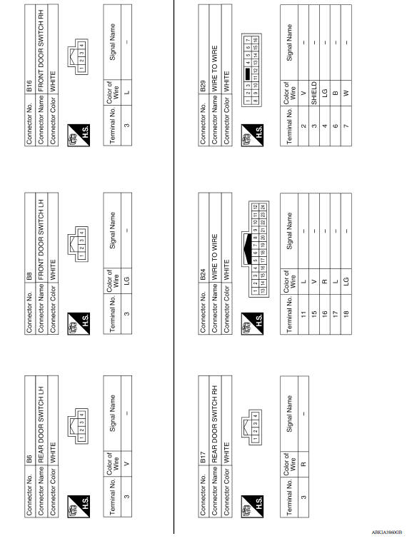
WIRING DIAGRAM
DOOR & LOCK SYSTEM
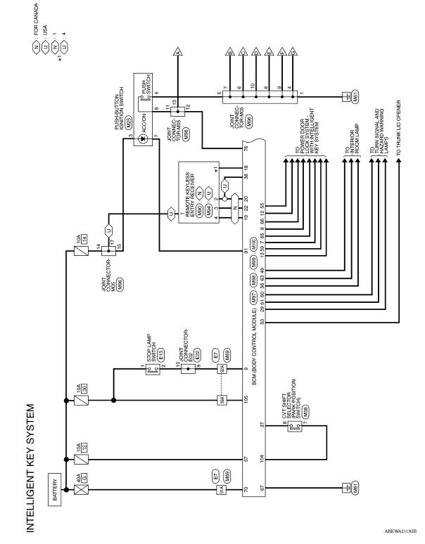
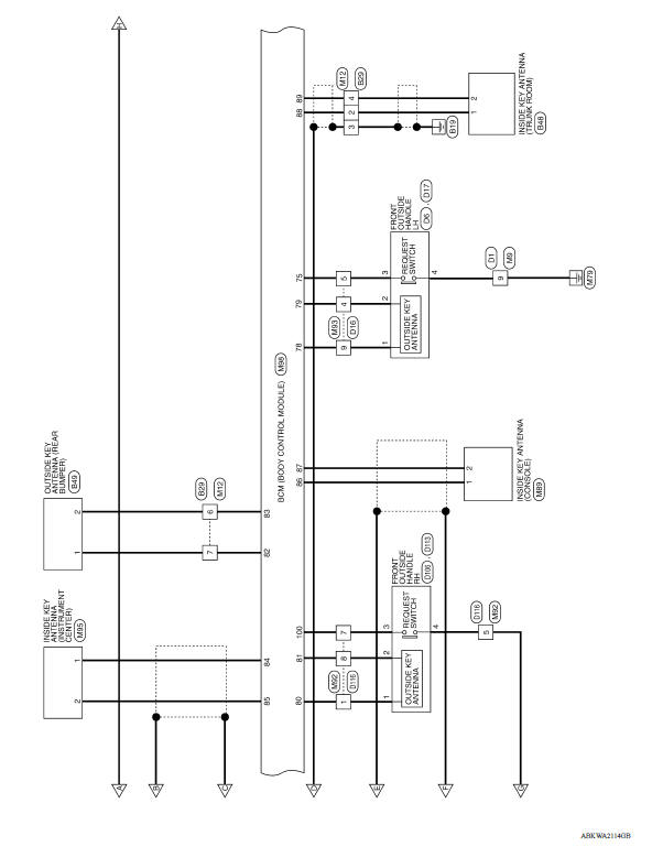
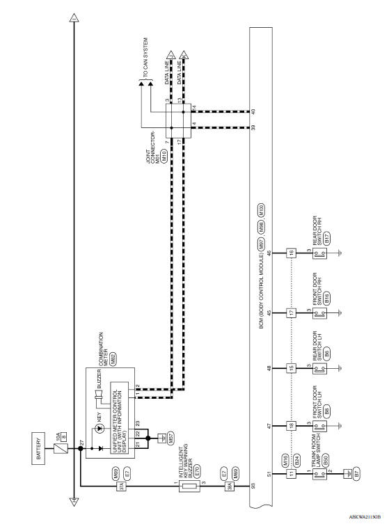
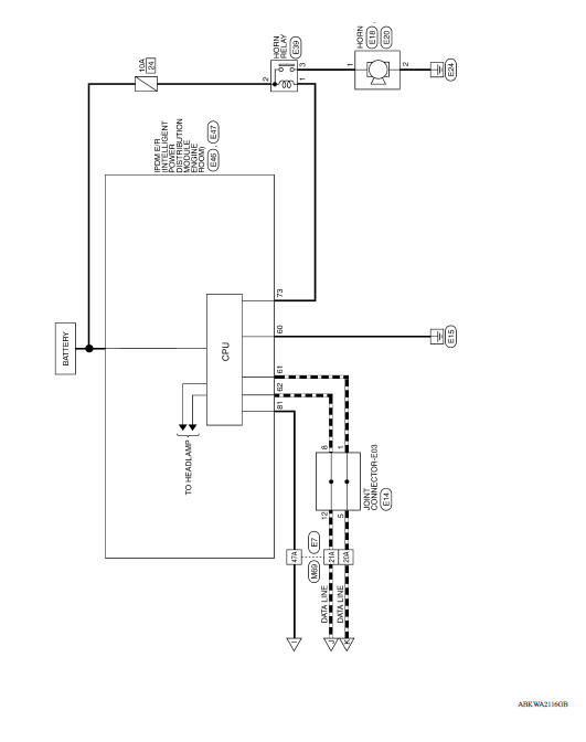
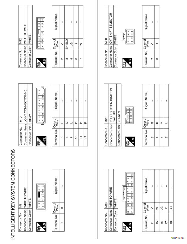
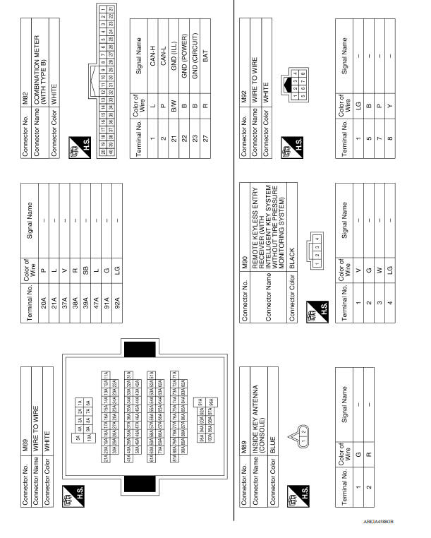
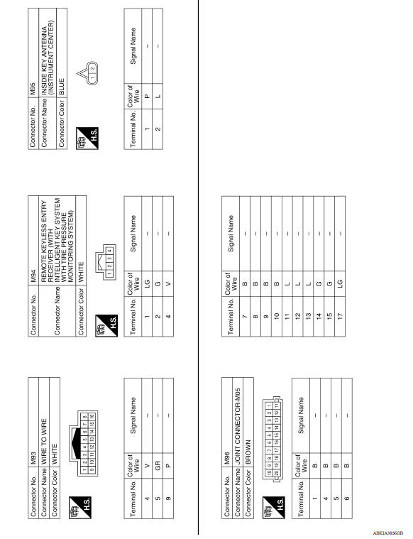
INTELLIGENT KEY SYSTEM
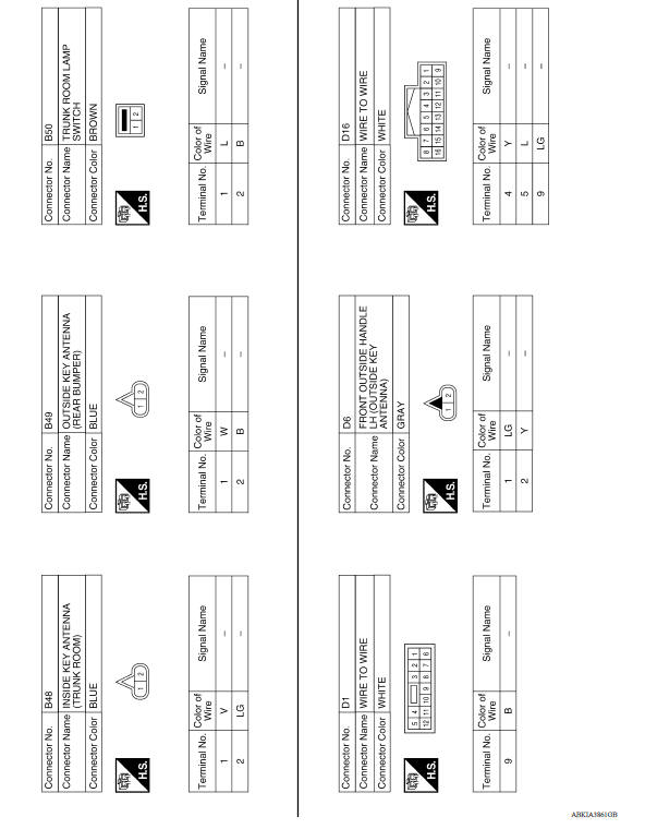
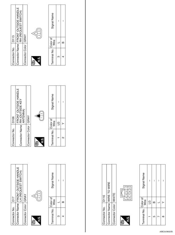
INTELLIGENT KEY SYSTEM : Wiring Diagram
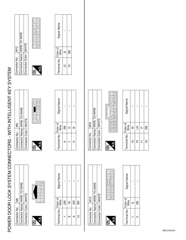
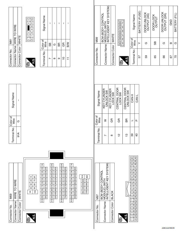
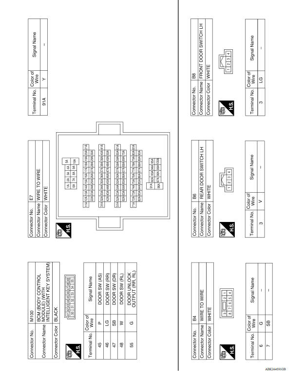
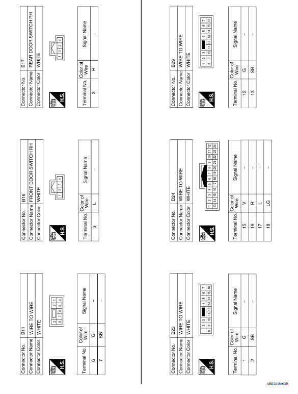
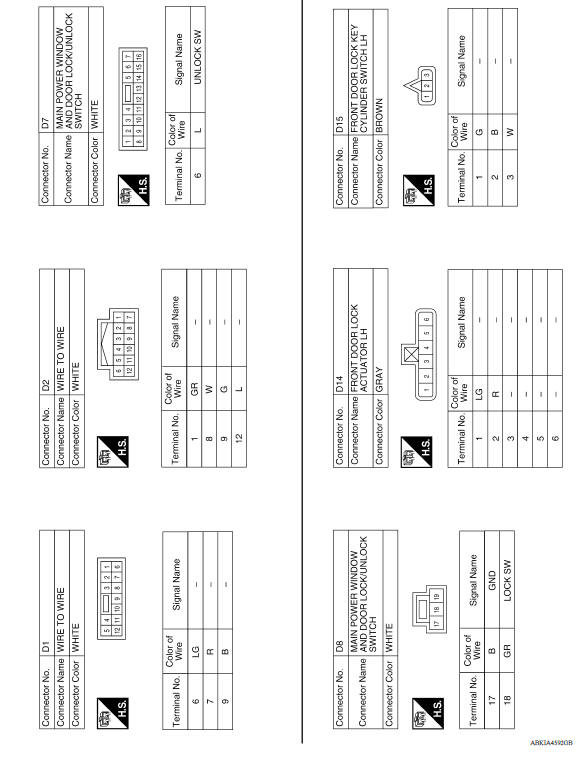
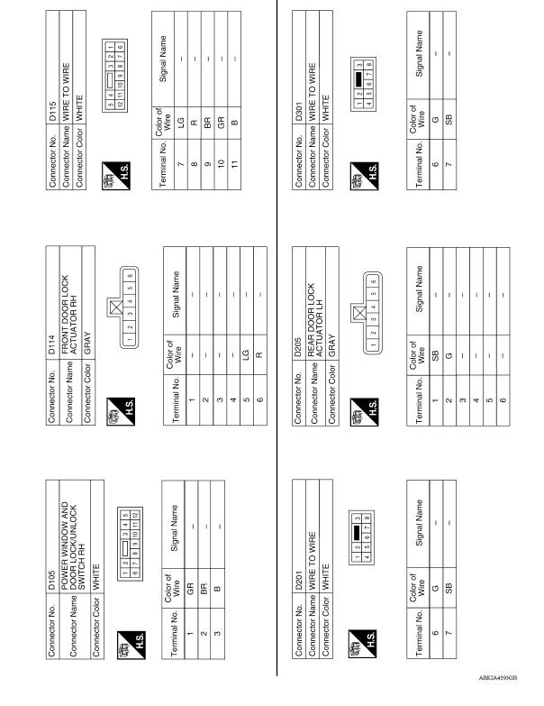
POWER DOOR LOCK SYSTEM
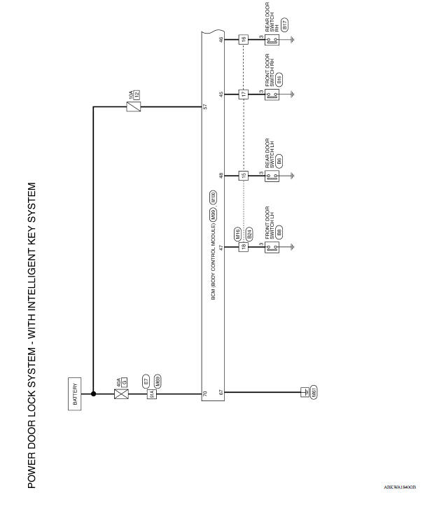
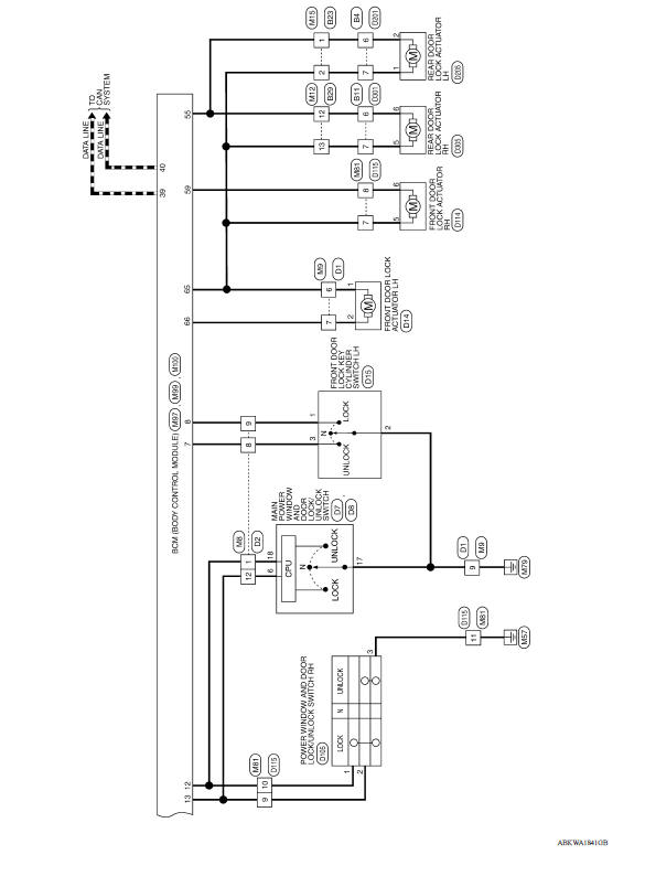
POWER DOOR LOCK SYSTEM : Wiring Diagram

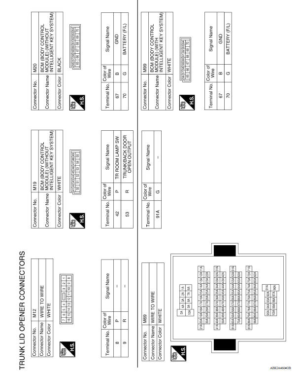
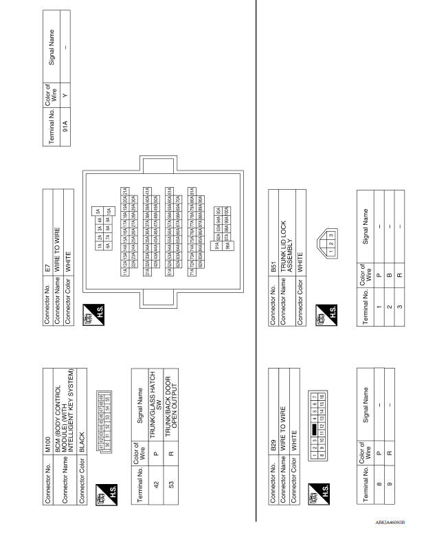
TRUNK LID OPENER SYSTEM
TRUNK LID OPENER SYSTEM : Wiring Diagram
BASIC INSPECTION
 Key reminder function
KEY REMINDER FUNCTION : System Description System Diagram BASIC OPERATION Key reminder is the function that prevents the key from being left in the vehicle. Key reminder has the following ...
Diagnosis and repair work flow
Work Flow OVERALL SEQUENCE DETAILED FLOW 1.GET INFORMATION FOR SYMPTOM Get detailed information from the customer about the symptom (the condition and the environment when the incide ...
Other materials:
Hood
1. Pull the hood lock release handle 1 located
below the instrument panel until the hood
springs up slightly.
2. Locate the lever 2 in between the hood and
grille and push the lever sideways with your
fingertips.
3. Raise the hood 3 .
4. Remove the support rod and insert it into the
...
U0140 Lost communication (BCM)
DTC Logic
DTC DETECTION LOGIC
DTC
Trouble diagnosis name
DTC detection condition
Possible causes
U0140
Lost Communication With Body
Control Module
When the ignition switch is ON,
TCM is unable to receive the
CAN communications signal
from BCM continuously ...
Categories
- Manuals Home
- Nissan Versa Owners Manual
- Nissan Versa Service Manual
- Video Guides
- Questions & Answers
- External Resources
- Latest Updates
- Most Popular
- Sitemap
- Search the site
- Privacy Policy
- Contact Us

0.0054