Nissan Versa (N17): A/C Indicator
Diagnosis Procedure
Regarding Wiring Diagram information, refer to HAC "Wiring Diagram" or HAC "Wiring Diagram".
1.CHECK A/C INDICATOR POWER SUPPLY
- Turn ignition switch ON.
- Check voltage between front air control harness connector and ground.
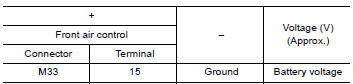
Is the inspection result normal?
YES >> Replace front air control. Refer to HAC "Removal and Installation".
NO >> Repair harness or connector between front air control and fuse.
 Blower fan on signal
Component Function Check 1.CHECK BLOWER FAN ON SIGNAL With CONSULT Turn ignition switch ON. Select "AIR CONDITIONER" of "BCM" using CONSULT. Select "FAN ON SIG" in "DATA MONITOR" mode, and ...
Front blower motor
Description The front blower motor utilizes a brush-less motor with a rotating magnet. Quietness is improved over previous motors where the brush was the point of contact and the coil rotated. ...
Other materials:
Vehicle Dynamic Control (VDC) off switch
The vehicle should be driven with the VDC system
on for most driving conditions.
If the vehicle is stuck in mud or snow, the VDC
system reduces the engine output to reduce
wheel spin. The engine speed will be reduced
even if the accelerator is depressed to the floor. If
maximum engine po ...
Service data and specifications
(SDS)
Periodical Maintenance Specification
ENGINE OIL CAPACITY (APPROXIMATE)
...
Categories
- Manuals Home
- Nissan Versa Owners Manual
- Nissan Versa Service Manual
- Video Guides
- Questions & Answers
- External Resources
- Latest Updates
- Most Popular
- Sitemap
- Search the site
- Privacy Policy
- Contact Us

0.0051