Nissan Versa (N17): Blower fan on signal
Component Function Check
1.CHECK BLOWER FAN ON SIGNAL
With CONSULT
- Turn ignition switch ON.
- Select "AIR CONDITIONER" of "BCM" using CONSULT.
- Select "FAN ON SIG" in "DATA MONITOR" mode, and check status under the
following condition.
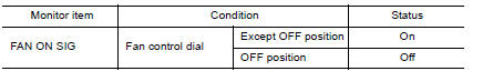
Is the inspection result normal?
YES >> Inspection End.
NO >> Refer to HAC "Diagnosis Procedure".
Diagnosis Procedure
Regarding Wiring Diagram information, refer to HAC "Wiring Diagram" or HAC "Wiring Diagram".
1.CHECK BLOWER FAN ON SIGNAL
- Turn ignition switch OFF.
- Disconnect front air control harness connector.
- Turn ignition switch ON.
- Check output waveform between front air control and ground with using
oscilloscope.
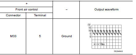
Is the inspection result normal?
YES >> Replace front air control. Refer to HAC "Removal and Installation".
NO >> GO TO 2.
2.CHECK BLOWER FAN ON SIGNAL CIRCUIT FOR OPEN
- Turn ignition switch OFF.
- Disconnect BCM connector.
- Check continuity front air control harness connector and BCM harness
connector.
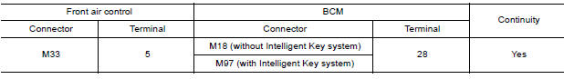
Is the inspection result normal?
YES >> GO TO 3.
NO >> Repair harness or connector.
3.CHECK BLOWER FAN ON SIGNAL CIRCUIT FOR SHORT
Check continuity between front air control harness connector and ground.
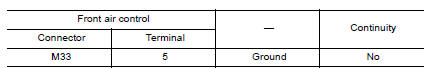
Is the inspection result normal?
YES >> Replace BCM. Refer to BCS "Removal and Installation" or BCS "Removal and Installation".
NO >> Repair harness or connector.
 A/C On signal
Component Function Check 1.CHECK A/C ON SIGNAL With CONSULT Turn ignition switch ON. Operate front blower motor. Select "AIR CONDITIONER" of "BCM" using CONSULT. Select "AIR COND SW" in ...
A/C Indicator
Diagnosis Procedure Regarding Wiring Diagram information, refer to HAC "Wiring Diagram" or HAC "Wiring Diagram". 1.CHECK A/C INDICATOR POWER SUPPLY Turn ignition switch O ...
Other materials:
Parking brake
WARNING
Be sure the parking brake is fully released
before driving. Failure to do so
can cause brake failure and lead to an
accident.
Do not release the parking brake from
outside the vehicle.
Do not use the shift lever in place of the
parking brake. When parking, be sure
the par ...
Diagnosis and repair work flow
Work Flow
OVERALL SEQUENCE
DETAILED FLOW
1. OBTAIN INFORMATION ABOUT SYMPTOM
Interview the customer to obtain as much information as possible about the
conditions and environment under
which the malfunction occurred.
>> GO TO 2
2. REPRODUCE THE MALFUNCTION INFORMATION
Check the ...
Categories
- Manuals Home
- Nissan Versa Owners Manual
- Nissan Versa Service Manual
- Video Guides
- Questions & Answers
- External Resources
- Latest Updates
- Most Popular
- Sitemap
- Search the site
- Privacy Policy
- Contact Us

0.0058