Nissan Versa (N17): A/C On signal
Component Function Check
1.CHECK A/C ON SIGNAL
With CONSULT
- Turn ignition switch ON.
- Operate front blower motor.
- Select "AIR CONDITIONER" of "BCM" using CONSULT.
- Select "AIR COND SW" in "DATA MONITOR" mode, and check status under the
following condition.
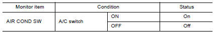
Is the inspection result normal?
YES >> Inspection End.
NO >> Refer to HAC "Diagnosis Procedure".
Diagnosis Procedure
Regarding Wiring Diagram information, refer to HAC "Wiring Diagram".
1.CHECK FUSE
- Turn ignition switch OFF.
- Check 10A fuse (No. 21, located in fuse block (J/B)].
NOTE: Refer to PG "Terminal Arrangement".
Is the inspection result normal?
YES >> GO TO 2.
NO >> Replace the blown fuse after repairing the affected circuit.
2.CHECK THERMO CONTROL AMP. POWER SUPPLY
- Turn ignition switch OFF.
- Disconnect thermo control amp. connector.
- Turn ignition switch ON.
- Check voltage between thermo control amp. harness connector and ground.
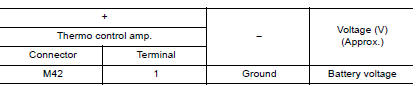
Is the inspection result normal?
YES >> GO TO 3.
NO >> Repair harness or connector between thermo control amp. and fuse.
3.CHECK THERMO CONTROL AMP. GROUND CIRCUIT FOR OPEN
- Turn ignition switch OFF.
- Check continuity between thermo control amp. harness connector and
ground
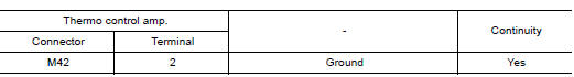
Is the inspection result normal?
YES >> GO TO 4.
NO >> Repair harness or connector.
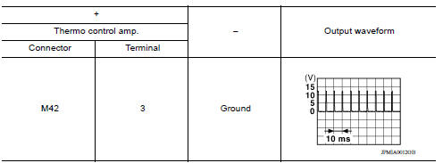
4.CHECK A/C ON SIGNAL
- Turn ignition switch ON.
- Check output waveform between thermo control amp. harness connector and
ground with using oscilloscope.
Is the inspection result normal?
YES >> GO TO 5.
NO >> GO TO 6.
5.CHECK FRONT AIR CONTROL
- Turn ignition switch OFF.
- Check front air control. Refer to HAC "Component Inspection".
Is the inspection result normal?
YES >> Replace thermo control amp. Refer to HAC "Removal and Installation".
NO >> Replace front air control. Refer to HAC "Removal and Installation".
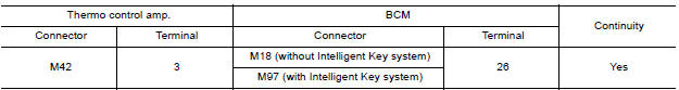
6.CHECK A/C ON SIGNAL CIRCUIT FOR OPEN
- Turn ignition switch OFF.
- Disconnect BCM and front air control connector.
- Check continuity between thermo control amp. harness connector and BCM
harness connector.
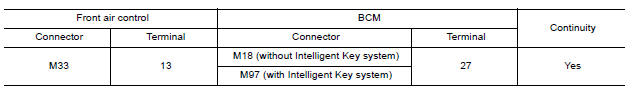
- Check continuity between front air control harness connector and BCM
harness connector.
Is the inspection result normal?
YES >> Replace BCM. Refer to BCS "Removal and Installation" or BCS "Removal and Installation".
NO >> Repair harness or connector.
Component Inspection
1.CHECK A/C CONTROL
Check continuity front air control terminals.
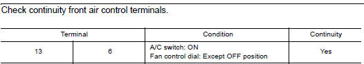
Is the inspection result normal?
YES >> Inspection End.
NO >> Replace front air control. Refer to HAC "Removal and Installation".
 Operation inspection
Work Procedure The purpose of the operation inspection is to check that the individual system operates normally. Check condition : Engine running at normal operating temperature. 1.CHECK F ...
Blower fan on signal
Component Function Check 1.CHECK BLOWER FAN ON SIGNAL With CONSULT Turn ignition switch ON. Select "AIR CONDITIONER" of "BCM" using CONSULT. Select "FAN ON SIG" in "DATA MONITOR" mode, and ...
Other materials:
Precautions
Precaution for Supplemental Restraint System
(SRS) "AIR BAG" and "SEAT BELT PRE-TENSIONER"
The Supplemental Restraint System such as "AIR BAG" and "SEAT BELT PRE-TENSIONER",
used along
with a front seat belt, helps to reduce the risk or severity of injury to the
driver and ...
Front suspension member
Exploded View
1. Front suspension member 2. Transverse link
Removal and Installation
REMOVAL
Remove the wheel and tire assemblies using power tool. Refer to WT
"Adjustment".
Remove transverse link. Refer to FSU-12, "Removal and Installation".
Remove steering o ...
Categories
- Manuals Home
- Nissan Versa Owners Manual
- Nissan Versa Service Manual
- Video Guides
- Questions & Answers
- External Resources
- Latest Updates
- Most Popular
- Sitemap
- Search the site
- Privacy Policy
- Contact Us

0.005