Nissan Versa (N17): A/C Unit assembly
Exploded View
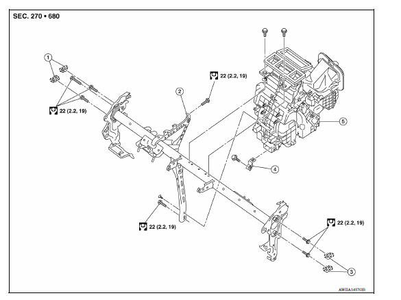
1. Cap 2. Steering member 3. Cap
4. Bracket 5. A/C unit assembly  Pawl
Pawl
Removal and Installation
CAUTION: Perform oil return operation before each refrigeration system disassembly. However, if a large amount of refrigerant or oil is detected, do not perform oil return operation. Refer to HA "Perform Oil Return Operation".
NOTE: When removing components such as hoses, tubes/lines, etc., cap or plug openings to prevent fluid from spilling.
REMOVAL
- Use refrigerant collecting equipment (for HFC-134a) to discharge the refrigerant. Refer to HA "Recycle Refrigerant".
- Drain engine coolant from cooling system. Refer to CO"Draining Engine Coolant".
- Remove low-pressure flexible hose and high-pressure pipe. Refer to HA
"Removal and Installation"
and HA "Removal and Installation" (if equipped).
CAUTION: Cap or wrap the joint of the A/C piping and expansion valve with suitable material such as vinyl tape to avoid the entry of air.
- Remove clamps and disconnect heater hoses from A/C unit assembly (if equipped).
- Remove the instrument panel assembly. Refer to IP "Removal and Installation".
- Disconnect drain hose from A/C unit assembly.
- Disconnect the necessary harness connectors and clips required to remove the steering member. Position the vehicle harness as necessary.
- Remove the BCM screws.
- Remove the J/B screws.
- Remove ground bolts.
- Remove the bolts, steering member and A/C unit assembly.
- Remove bolts and A/C unit assembly from the steering member.
INSTALLATION
Installation is in the reverse order of removal.
CAUTION:
- Do not reuse O-rings.
- Apply A/C oil to the O-rings of the low-pressure flexible hose and high pressure flexible pipe for installation.
- After charging the refrigerant, check for leaks. Refer to HA "Leak Test".
NOTE: Refer to CO "Refilling Engine Coolant" when filling radiator with engine coolant.
 Refrigerant pressure sensor
Removal and Installation CAUTION: Perform oil return operation before each refrigeration system disassembly. However, if a large amount of refrigerant or oil is detected, do not perform oil retu ...
Evaporator
Removal and Installation REMOVAL Remove A/C unit assembly. Refer to HA "Removal and Installation". Disassemble A/C unit assembly and the evaporator assembly. Remove thermo control a ...
Other materials:
Malfunction indicator lamp
Component Function Check
1.CHECK MIL FUNCTION
Turn ignition switch ON.
Make sure that MIL lights up.
Is the inspection result normal?
YES >> INSPECTION END
NO >> Go to EC, "Diagnosis Procedure".
Diagnosis Procedure
1.CHECK DTC
Check that DTC UXXXX is not display ...
Component parts
Component Parts Location
1 BCM (view with instrument panel removed)
2 Remote keyless entry receiver (view
with instrument panel removed)
3 Transmitter
4 Combination meter (with type A) 5 Combination meter (with type B)
Component Description
Component parts
Function
...
Categories
- Manuals Home
- Nissan Versa Owners Manual
- Nissan Versa Service Manual
- Video Guides
- Questions & Answers
- External Resources
- Latest Updates
- Most Popular
- Sitemap
- Search the site
- Privacy Policy
- Contact Us

0.0054