Nissan Versa (N17): Evaporator
Removal and Installation
REMOVAL
- Remove A/C unit assembly. Refer to HA "Removal and Installation".
- Disassemble A/C unit assembly and the evaporator assembly.
- Remove thermo control amp. from evaporator assembly.
CAUTION: If reusing the evaporator, mark the location of the thermo control amp. for installation.
- Remove bolts and the evaporator.
INSTALLATION
Installation is in the reverse order of removal.
CAUTION:
- Do not reuse O-rings.
- Apply A/C oil to the new O-rings for installation.
- When installing the intake sensor (automatic air conditioner) or the thermo control amp. (manual air conditioner), place in the same position as before replacement.
- Do not rotate the bracket insertion part when removing and installing the intake sensor (automatic air conditioner) or the thermo control amp. (manual air conditioner).
- Perform oil adjusting procedure after installing new evaporator. Refer to HA "Oil Adjusting Procedure for Components Replacement Except Compressor".
- After charging the A/C refrigerant, check for leaks. Refer to HA "Leak Test".
UNIT DISASSEMBLY AND ASSEMBLY
A/C UNIT ASSEMBLY
Exploded View
UNIT DISASSEMBLY
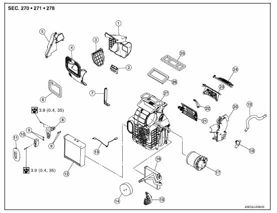
1. Rear intake case 2. Sub intake door 3. Intake door 4. Front intake case 5. Foot duct (RH) 6. Packing 7. Filter cover 8. Evaporator pipe assembly 9. O-ring 10. Expansion valve 11. Grommet 12. Evaporator 13. Intake sensor 14. Packing 15. Heater pipe flange 16. Heater core 17. Blower motor 18. Aspirator 19. Aspirator hose 20. Foot duct (LH) 21. Air mix door 22. Center plate 23. Foot door 24. Ventilator door 25. Packing 26. Packing 27. A/C unit case assembly
SERVICE DATA AND SPECIFICATIONS (SDS)
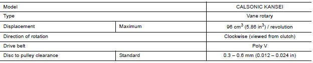
Compressor
Oil
|
Application |
HR16DE | |
| Type | NISSAN A/C System Oil Type R (DH-PR) | |
| Capacity | Total in system | 120 m (4.1 US fl oz, 4.2 lmp fl oz) |
| Compressor (service part) charging | Refer to HA "Description". | |
Refrigerant 
 A/C Unit assembly
Exploded View 1. Cap 2. Steering member 3. Cap 4. Bracket 5. A/C unit assembly Pawl Removal and Installation CAUTION: Perform oil return operation before each refrigeration system disassemb ...

Other materials:
P0717 Input speed sensor A
DTC Logic
DTC DETECTION LOGIC
DTC
Trouble diagnosis name
DTC detection condition
Possible causes
P0717
Input/Turbine Speed Sensor "A"
Circuit No Signal
Under the following diagnosis
conditions, the input speed sensor
value is less than 600 rpm
continuousl ...
U0300 Can communication data
Description
CAN (Controller Area Network) is a serial communication line for real-time
application. It is an on-vehicle multiplex
communication line with high data communication speed and excellent malfunction
detection ability.
Many electronic control units are equipped onto a vehicle, an ...
Categories
- Manuals Home
- Nissan Versa Owners Manual
- Nissan Versa Service Manual
- Video Guides
- Questions & Answers
- External Resources
- Latest Updates
- Most Popular
- Sitemap
- Search the site
- Privacy Policy
- Contact Us

0.005