Nissan Versa (N17): Basic inspection
Work Procedure
1.INSPECTION START
1. Check service records for any recent repairs that may indicate a related malfunction, or a current need for scheduled maintenance.
2. Open engine hood and check the following:
- Harness connectors for improper connections
- Wiring harness for improper connections, pinches and cut
- Vacuum hoses for splits, kinks and improper connections
- Hoses and ducts for leaks
- Air cleaner clogging
- Gasket
3. Confirm that electrical or mechanical loads are not applied.
- Headlamp switch is OFF.
- Air conditioner switch is OFF.
- Rear window defogger switch is OFF.
- Steering wheel is in the straightahead position, etc.
4. Start engine and warm it up until engine coolant temperature indicator points to the middle of gauge.
Ensure engine stays below 1,000 rpm.

5. Run engine at about 2,000 rpm for about 2 minutes under no load.
6. Make sure that no DTC is displayed with CONSULT or GST.
Is any DTC detected?
YES >> GO TO 2.
NO >> GO TO 3.
2.REPAIR OR REPLACE
Repair or replace components as necessary according to corresponding Diagnostic Procedure.
>> GO TO 3
3.CHECK TARGET IDLE SPEED
1. Run engine at about 2,000 rpm for about 2 minutes under no load.
2. Rev engine (2,000 to 3,000 rpm) two or three times under no load, then run engine at idle speed for about 1 minute.
3. Check idle speed.
For procedure, refer to EC, "Inspection".
For specification, refer to EC, "Idle Speed".
Is the inspection result normal?
YES >> GO TO 10.
NO >> GO TO 4.

4.PERFORM ACCELERATOR PEDAL RELEASED POSITION LEARNING
- Stop engine.
- Perform EC, "Work Procedure".
>> GO TO 5.
5.PERFORM THROTTLE VALVE CLOSED POSITION LEARNING
Perform EC, "Work Procedure".
>> GO TO 6.
6.PERFORM IDLE AIR VOLUME LEARNING
Perform EC, "Work Procedure".
Is Idle Air Volume Learning carried out successfully?
YES >> GO TO 7.
NO >> Follow the instruction of IDLE AIR VOLUME LEARNING. Then GO TO 4.
7.CHECK TARGET IDLE SPEED AGAIN
- Start engine and warm it up to normal operating temperature.
- Check idle speed.
For procedure, refer to EC, "Inspection".
For specification, refer to EC, "Idle Speed".
Is the inspection result normal?
YES >> GO TO 10.
NO >> GO TO 8.
8.DETECT MALFUNCTIONING PART
Check the Following.
- Check intake camshaft position sensor (PHASE) and circuit.
- Check crankshaft position sensor (POS) and circuit.
Is the inspection result normal?
YES >> GO TO 9.
NO >> Repair or replace. Then GO TO 4.
9.CHECK ECM FUNCTION
- Substitute another knowngood ECM to check ECM function. (ECM may be the cause of an incident, but this is a rare case.)
- Perform initialization and registration of all NATS ignition key IDs.
>> GO TO 4.
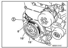
10.CHECK IGNITION TIMING
- Run engine at idle.
- Check ignition timing with a timing light.
Timing indicator (1)
Is the inspection result normal?
YES >> GO TO 19.
NO >> GO TO 11.
11.PERFORM ACCELERATOR PEDAL RELEASED POSITION LEARNING
- Stop engine.
- Perform EC, "Work Procedure".
>> GO TO 12.
12.PERFORM THROTTLE VALVE CLOSED POSITION LEARNING
Perform EC "Work Procedure".
>> GO TO 13.
13.PERFORM IDLE AIR VOLUME LEARNING
Perform EC, "Work Procedure".
Is idle air volume learning carried out successfully?
YES >> GO TO 14.
NO >> Follow the instruction of IDLE AIR VOLUME LEARNING. Then GO TO 4.
14.CHECK TARGET IDLE SPEED AGAIN
- Start engine and warm it up to normal operating temperature.
- Check idle speed.
For procedure, refer to EC, "Inspection".
For specification, refer to EC, "Idle Speed".
Is the inspection result normal?
YES >> GO TO 15.
NO >> GO TO 17.
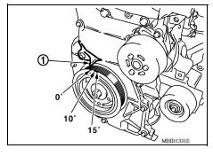
15.CHECK IGNITION TIMING AGAIN
- Run engine at idle.
- Check ignition timing with a timing light.
For procedure, refer to EC, "Inspection".
For specification, refer to EC, "Ignition Timing".
Timing indicator (1)
Is the inspection result normal?
YES >> GO TO 19.
NO >> GO TO 16.
16.CHECK TIMING CHAIN INSTALLATION
Check timing chain installation. Refer to EM, "Removal and Installation".
Is the inspection result normal?
YES >> GO TO 17.
NO >> Repair the timing chain installation. Then GO TO 4.
17.DETECT MALFUNCTIONING PART
Check the following.
- Check intake camshaft position sensor (PHASE) and circuit. Refer to EC "DTC Logic".
- Check crankshaft position sensor (POS) and circuit. Refer to EC "DTC Logic".
Is the inspection result normal?
YES >> GO TO 18.
NO >> Repair or replace. Then GO TO 4.
18.CHECK ECM FUNCTION
- Substitute another knowngood ECM to check ECM function. (ECM may be the cause of an incident, but this is a rare case.)
- Perform initialization of NATS system and registration of all NATS ignition key IDs.
>> GO TO 4.
19.INSPECTION END
If ECM is replaced during this BASIC INSPECTION procedure, perform EC, "Work Procedure".
>> INSPECTION END
 Mixture ratio selflearning value
clear
Mixture ratio selflearning value
clear
Description This describes how to erase the mixture ratio selflearning value. For the actual procedure, follow the instructions in "Diagnosis Procedure". Work Procedure 1.START With CONSULT ...
Fuel pressure check
Work Procedure FUEL PRESSURE RELEASE 1.FUEL PRESSURE RELEASE With CONSULT Turn ignition switch ON. Perform "FUEL PRESSURE RELEASE" in "WORK SUPPORT" mode with CONSULT. Start engine. Aft ...
Other materials:
Security systems (if so equipped)
Your vehicle has one type of security systems:
NISSAN Vehicle Immobilizer System
NISSAN vehicle immobilizer system
The NISSAN Vehicle Immobilizer System will not
allow the engine to start without the use of a
registered key.
If the engine fails to start using a registered key
(for ex ...
EVAP control system pressure sensor
Exploded View
1. EVAP control system pressure sensor 2. O-ring 3. EVAP canister
Removal and Installation
NOTE:
The EVAP canister system pressure sensor can be removed without removing the
EVAP canister.
REMOVAL
Remove the EVAP canister protector cover.
Disconnect EVAP canister purg ...
Categories
- Manuals Home
- Nissan Versa Owners Manual
- Nissan Versa Service Manual
- Video Guides
- Questions & Answers
- External Resources
- Latest Updates
- Most Popular
- Sitemap
- Search the site
- Privacy Policy
- Contact Us

0.005