Nissan Versa (N17): Blower fan resistor
Exploded View
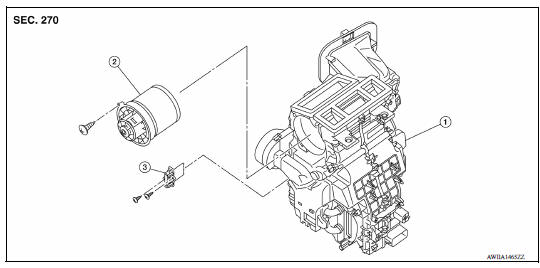
1. A/C unit assembly 2. Blower motor 3. Blower fan resistor
Removal and Installation
REMOVAL
- Remove instrument panel assembly. Refer to IP "Removal and Installation".
- Disconnect harness connector from the blower fan resistor.
- Remove screws and blower fan resistor.
INSTALLATION
Installation is in the reverse order of removal.
DOOR CABLE
Exploded View
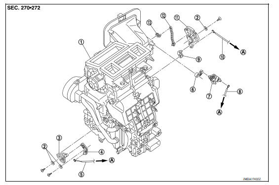
1. A/C unit assembly 2. Plate 3. Air mix door link 2 4. Air mix door link 1 5. Air mix door cable 6. Intake door lever 7. Intake door link 8. Intake door cable 9. Foot door lever 10. Mode door cable 11. Main link 12. Ventilator door rod 13. Ventilator door lever A. To A/C control
 Refrigerant pressure sensor
Removal and Installation for Refrigerant Pressure Sensor REMOVAL CAUTION: Do not damage the condenser fins. Perform lubricant return operation before each refrigeration system disassembly. ...
Intake door cable
INTAKE DOOR CABLE : Removal and Installation REMOVAL Remove instrument panel assembly. Refer to IP "Removal and Installation". Disconnect intake door cable from A/C control. Disc ...
Other materials:
NISSAN Intelligent Key (if so equipped)
WARNING
Radio waves could adversely affect
electric medical equipment. Those who
use a pacemaker should contact the
electric medical equipment manufacturer
for the possible influences before
use.
The Intelligent Key transmits radio
waves when the buttons are pressed.
The FAA ad ...
Maintenance under severe operating conditions
The maintenance intervals shown on the preceding pages are for normal
operating conditions. If the vehicle is mainly operated under severe driving
conditions as shown below, more frequent maintenance must be performed on the
following items as shown in the table.
Severe driving conditions
...
Categories
- Manuals Home
- Nissan Versa Owners Manual
- Nissan Versa Service Manual
- Video Guides
- Questions & Answers
- External Resources
- Latest Updates
- Most Popular
- Sitemap
- Search the site
- Privacy Policy
- Contact Us

0.0044