Nissan Versa (N17): Refrigerant pressure sensor
Removal and Installation for Refrigerant Pressure Sensor
REMOVAL
CAUTION:
- Do not damage the condenser fins.
- Perform lubricant return operation before each refrigeration
system disassembly. However, if a large amount of refrigerant
or lubricant is detected, do not perform lubricant return operation.
Refer to HA "Perform Oil Return Operation".
- Move air guide aside.
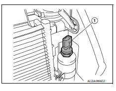
- Disconnect the harness connector from the refrigerant pressure sensor.
- Remove the refrigerant pressure sensor (1) from the liquid tank on the condenser.
INSTALLATION
Installation is in the reverse order of removal.
CAUTION:
- Replace O-ring with new one. Then apply compressor oil to them when installing.
- Check for leakages when recharging refrigerant. Refer to HA "Leak Test".
 Front air control
Exploded View 1. Mode door cable 2. Illumination bulb 3. Air mix door cable 4. Front air control 5. Intake door cable 6. Intake door lever knob 7. Control panel bezel 8. Mode dial 9. Temperat ...
Blower fan resistor
Exploded View 1. A/C unit assembly 2. Blower motor 3. Blower fan resistor Removal and Installation REMOVAL Remove instrument panel assembly. Refer to IP "Removal and Installation&qu ...
Other materials:
Oil cooler
Exploded View
1. Radiator hose (upper) 2. Hose clamp 3. Radiator hose (lower)
4. Hose clamp 5. Water hose 6. Oil cooler
7. Connector bolt 8. Water hose 9. Oring
A. To radiator (upper side) B. To radiator (lower side) 10. Relief valve
Removal and Installation
REMOVAL
NOTE:
When removing co ...
Front wheel hub and knuckle
Inspection
Check the axle and suspension parts for excessive play, wear, or damage.
Shake each front wheel to check for excessive play as shown.
FRONT WHEEL BEARING INSPECTION
Move wheel hub and bearing assembly in the axial direction by hand. Make
sure the axial end play is withi ...
Categories
- Manuals Home
- Nissan Versa Owners Manual
- Nissan Versa Service Manual
- Video Guides
- Questions & Answers
- External Resources
- Latest Updates
- Most Popular
- Sitemap
- Search the site
- Privacy Policy
- Contact Us

0.0048