Nissan Versa (N17): Front air control
Exploded View
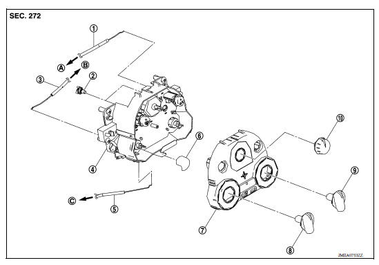
1. Mode door cable 2. Illumination bulb 3. Air mix door cable 4. Front air control 5. Intake door cable 6. Intake door lever knob 7. Control panel bezel 8. Mode dial 9. Temperature dial 10. Fan control dial A. To mode door link B. To air mix door link C. To intake door link
Removal and Installation
REMOVAL
- Remove A/C finisher. Refer to IP "Removal and Installation".
- Remove the air mix door cable from the A/C unit assembly. Refer to HAC "AIR MIX DOOR CABLE : Removal and Installation".
- Remove the mode door cable from the A/C unit assembly. Refer to HAC "MODE DOOR CABLE : Removal and Installation".
- Remove the intake door cable from the A/C unit assembly. Refer to HAC "INTAKE DOOR CABLE : Removal and Installation".
- Remove the front air control screws.
- Remove the front air control.
INSTALLATION
Installation is in the reverse order of removal.
 Compressor does not operate
Description SYMPTOM Compressor does not operate. Diagnosis Procedure NOTE: Perform self-diagnosis with CONSULT before performing symptom diagnosis. If any malfunction result or DTC is d ...
Refrigerant pressure sensor
Removal and Installation for Refrigerant Pressure Sensor REMOVAL CAUTION: Do not damage the condenser fins. Perform lubricant return operation before each refrigeration system disassembly. ...
Other materials:
Service data and specifications
(SDS)
General Specification
CAUTION:
Use only Genuine NISSAN Matic S ATF. Do not mix with other ATF.
Using ATF other than Genuine NISSAN Matic S ATF will cause
deterioration of driveability and A/T durability, and may damage
the A/T, which is not covered by the warranty.
*1: ...
P0711 Transmission fluid temperature
sensor A
DTC Logic
DTC DETECTION LOGIC
DTC
Trouble diagnosis name
DTC detection condition
Possible causes
P0711
Transmission Fluid Temperature
Sensor A Circuit Range/
Performance
Under the following diagnosis conditions, CVT
fluid temperature does not rise to 10C (5 ...
Categories
- Manuals Home
- Nissan Versa Owners Manual
- Nissan Versa Service Manual
- Video Guides
- Questions & Answers
- External Resources
- Latest Updates
- Most Popular
- Sitemap
- Search the site
- Privacy Policy
- Contact Us

0.0049