Nissan Versa (N17): Compressor does not operate
Description
SYMPTOM
Compressor does not operate.
Diagnosis Procedure
NOTE:
- Perform self-diagnosis with CONSULT before performing symptom diagnosis. If any malfunction result or DTC is detected, perform the corresponding diagnosis.
- Check that refrigerant system is fully charged. If the refrigerant charge is low, perform the inspection for refrigerant leakage
1.CHECK MAGNET CLUTCH OPERATION
Check magnet clutch. Refer to HAC "Component Function Check".
Does it operate normally?
YES >> GO TO 2.
NO >> Repair or replace malfunctioning parts.
2.CHECK REFRIGERANT PRESSURE SENSOR
Check refrigerant pressure sensor. Refer to EC "Component Function Check".
Is the inspection result normal?
YES >> GO TO 3.
NO >> Repair or replace malfunctioning parts.
3.CHECK A/C ON SIGNAL
Check A/C ON signal. Refer to HAC "Component Function Check".
Is the inspection result normal?
YES >> GO TO 4.
NO >> Repair or replace malfunctioning parts.
4.CHECK BLOWER FAN ON SIGNAL
Check blower fan ON signal. Refer to HAC "Component Function Check".
Is the inspection result normal?
YES >> GO TO 5.
NO >> Repair or replace malfunctioning parts
5.CHECK BCM OUTPUT SIGNAL
With CONSULT
- Select "DATA MONITOR" mode of "ECM" using CONSULT.
- Select "AIR COND SIG" and "HEATER FAN SW", and check status under the
following conditions.
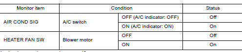
Is the inspection result normal?
YES >> Replace IPDM E/R. Refer to PCS "Removal and Installation".
NO >> Replace BCM. Refer to BCS "Removal and Installation" or BCS "Removal and Installation".
UNIT REMOVAL AND INSTALLATION
 Insufficient heating
Description Symptom Insufficient heating No warm air comes out. (Air flow volume is normal.) Diagnosis Procedure NOTE: Perform self-diagnosis with CONSULT before performing symptom diagn ...
Front air control
Exploded View 1. Mode door cable 2. Illumination bulb 3. Air mix door cable 4. Front air control 5. Intake door cable 6. Intake door lever knob 7. Control panel bezel 8. Mode dial 9. Temperat ...
Other materials:
Windows
Power windows (if so equipped)
WARNING
Make sure that all passengers have
their hands, etc. inside the vehicle while
it is in motion and before closing the
windows. Use the window lock switch to
prevent unexpected use of the power
windows
To help avoid risk of injury or death
thr ...
U1117 Lost communication (ABS)
Description
CAN (Controller Area Network) is a serial communication line for real-time
application. It is an on-vehicle multiplex
communication line with high data communication speed and excellent malfunction
detection ability.
Many electronic control units are equipped onto a vehicle, and ...
Categories
- Manuals Home
- Nissan Versa Owners Manual
- Nissan Versa Service Manual
- Video Guides
- Questions & Answers
- External Resources
- Latest Updates
- Most Popular
- Sitemap
- Search the site
- Privacy Policy
- Contact Us

0.0048