Nissan Versa (N17): C1115 ABS Sensor [abnormal signal]
DTC Logic
DTC DETECTION LOGIC
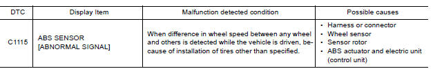
DTC CONFIRMATION PROCEDURE
1.CHECK SELF DIAGNOSTIC RESULT
With CONSULT.
- Start engine and drive vehicle at approximately 30 km/h (19 MPH) or more for approximately 1 minute.
- Perform self diagnostic result.
Is DTC C1115 detected?
YES >> Proceed to diagnosis procedure. Refer to BRC "Diagnosis Procedure".
NO >> Inspection End.
Diagnosis Procedure
Regarding Wiring Diagram information, refer to BRC "Wiring Diagram".
CAUTION: Do not check between wheel sensor terminals.
1.CONNECTOR INSPECTION
- Disconnect ABS actuator and electric unit (control unit) connector E33 and wheel sensor connector of wheel with DTC.
- Check terminals for deformation, disconnection, looseness or damage.
Is the inspection result normal?
YES >> GO TO 2
NO >> Repair or replace as necessary.
2.CHECK WHEEL SENSOR OUTPUT SIGNAL
- Connect ABS active wheel sensor tester (J-45741) to wheel sensor using appropriate adapter.
- Turn on the ABS active wheel sensor tester power switch.
NOTE: The green POWER indicator should illuminate. If the POWER indicator does not illuminate, replace the battery in the ABS active wheel sensor tester before proceeding.
- Spin the wheel of the vehicle by hand and observe the red SENSOR
indicator on the ABS active wheel
sensor tester. The red SENSOR indicator should flash on and off to indicate
an output signal.
NOTE: If the red SENSOR indicator illuminates but does not flash, reverse the polarity of the tester leads and retest.
Does the ABS active wheel sensor tester detect a signal?
YES >> GO TO 3
NO >> Replace the wheel sensor. Refer to BRC "FRONT WHEEL SENSOR : Removal and Installation" (front) or BRC "REAR WHEEL SENSOR : Removal and Installation" (rear).
3.CHECK TIRES
Check the inflation pressure, wear and size of each tire.
Is the inspection result normal?
YES >> GO TO 4
NO >> Adjust tire pressure, or replace tire(s).
4.CHECK WIRING HARNESS FOR SHORT CIRCUIT
Check continuity between wheel sensor connector terminals and ground of wheel
with DTC. 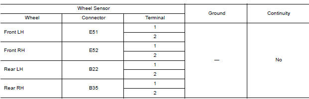
Is the inspection result normal?
YES >> GO TO 5
NO >> Repair the circuit.
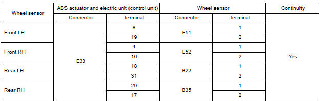
5.CHECK WIRING HARNESS FOR OPEN CIRCUIT
Check continuity between ABS actuator and electric unit (control unit)
connector E33 and wheel sensor connector
of wheel with DTC.
Is the inspection result normal?
YES >> Replace the ABS actuator and electric unit (control unit). Refer to BRC-108, "Removal and Installation".
NO >> Repair the circuit.
 C1111 Pump motor
Other materials:
Fuel filler lid lock
FUEL FILLER LID LOCK : Removal and Installation
REMOVAL
1. Fully open fuel filler lid.
2. Remove trunk side finisher (LH). Refer to INT "TRUNK SIDE FINISHER :
Removal and Installation".
3. Release pawls (A) and remove fuel filler lid lock assembly (1)
from opening.
CAUTION:
Be car ...
Front regulator
Exploded View
1. Front door panel 2. Front door lower sash (front) 3. Front door glass run
4. Front door sealing screen 5. Front door power window motor 6. Front door
regulator
7. Front door glass 8. Front door lower sash (rear) 9. Regulator seal (manual
window)
10. Snap pin (manual wind ...
Categories
- Manuals Home
- Nissan Versa Owners Manual
- Nissan Versa Service Manual
- Video Guides
- Questions & Answers
- External Resources
- Latest Updates
- Most Popular
- Sitemap
- Search the site
- Privacy Policy
- Contact Us

0.006