Nissan Versa (N17): Diagnosis and repair workflow
Workflow
OVERALL SEQUENCE
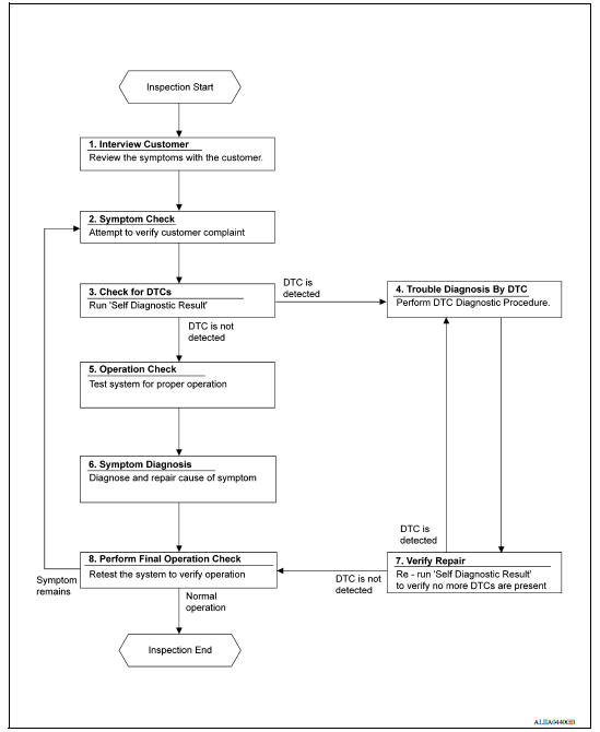
DETAILED FLOW
1.INTERVIEW CUSTOMER
Interview the customer to obtain as much information as possible about the conditions and environment under which the malfunction occurred.
>> GO TO 2.
2.SYMPTOM CHECK
Verify symptoms.
>> GO TO 3.
3.CHECK FOR DTCS
With CONSULT
- Turn ignition switch ON.
- Select "Self Diagnostic Result" mode of "BCM" using CONSULT.
- Check DTC.
Is any DTC detected?
YES >> GO TO 4.
NO >> GO TO 5.
4.PERFORM DTC DIAGNOSTIC PROCEDURE
Perform the diagnostic procedure for the detected DTC. Refer to BCS"DTC Inspection Priority Chart" or BCS "DTC Inspection Priority Chart".
>> GO TO 7.
5.OPERATION CHECK
Perform the operation check. Refer to HAC "Work Procedure".
>> GO TO 6.
6.SYMPTOM DIAGNOSIS
Check the symptom diagnosis table. Refer to HA "Symptom Table".
>> GO TO 8.
7.VERIFY REPAIR.
With CONSULT
- Turn ignition switch ON.
- Select "Self Diagnostic Result" mode of "BCM" using CONSULT.
- Check DTC.
Is any DTC detected?
YES >> GO TO 4.
NO >> GO TO 8.
8.PERFORM FINAL OPERATION CHECK
Perform the operation check. Refer to HAC "Work Procedure".
Does it operate normally?
YES >> Inspection End.
NO >> GO TO 2.
 Refrigeration system
Refrigerant Cycle REFRIGERANT FLOW The refrigerant flows in the standard pattern, that is, through the compressor, the condenser with liquid tank, through the evaporator, and back to the compress ...
Refrigerant
Description CONNECTION OF SERVICE TOOLS AND EQUIPMENT 1. Shut-off valve 2. A/C service valve 3. Recovery/recycling/recharging equipment 4. Vacuum pump 5. Manifold gauge set 6. Refrigerant con ...
Other materials:
Maintenance under severe operating conditions
The maintenance intervals shown on the preceding pages are for normal
operating conditions. If the vehicle is mainly operated under severe driving
conditions as shown below, more frequent maintenance must be performed on the
following items as shown in the table.
Severe driving conditions
...
Rear door finisher
Exploded View
1. Rear door panel 2. Rear door finisher 3. Rear power window switch finisher
(if
equipped)
4. Grommet Clip
Metal clip
Pawl
Removal and Installation
REMOVAL
Fully open rear door window.
Remove rear door finisher clip (A).
Remove rear power window switch and f ...
Categories
- Manuals Home
- Nissan Versa Owners Manual
- Nissan Versa Service Manual
- Video Guides
- Questions & Answers
- External Resources
- Latest Updates
- Most Popular
- Sitemap
- Search the site
- Privacy Policy
- Contact Us

0.0053