Nissan Versa (N17): P0999 Shift solenoid F
DTC Logic
DTC DETECTION LOGIC
| DTC | Trouble diagnosis name | DTC detection condition | Possible causes |
| P0999 | Shift solenoid F control circuit high | The TCM low brake solenoid valve current
monitor reading is 200 mA or less continuously
for 200 msec or more under the following diagnosis
conditions: Diagnosis conditions - Solenoid valve output current: 750 mA or more - GND short diagnosis of the solenoid valve circuit is not satisfied. - TCM power supply voltage: More than 11 V |
- Harness or connector
(Low brake solenoid valve circuit is
open or shorted to power supply) - Low brake solenoid valve |
DTC CONFIRMATION PROCEDURE
1.PREPARATION BEFORE WORK
If another "DTC CONFIRMATION PROCEDURE" occurs just before, turn ignition switch OFF and wait for at least 10 seconds, then perform the next test.
>> GO TO 2.
2.CHECK DTC DETECTION
- Start the engine.
- Shift the selector lever to "D" position and wait for 5 seconds or more.
- Check the first trip DTC.
Is "P0999" detected?
YES >> Go to TM "Diagnosis Procedure".
NO >> INSPECTION END
Diagnosis Procedure
1.CHECK CIRCUIT BETWEEN TCM AND CVT UNIT
- Turn ignition switch OFF.
- Disconnect TCM connector and CVT unit connector.
- Check continuity between TCM harness connector terminal and CVT unit
harness connector terminal.
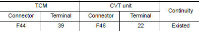
Is the inspection result normal?
YES >> GO TO 2.
NO >> Repair or replace malfunctioning parts.
2.CHECK LOW BRAKE SOLENOID VALVE
Check low brake solenoid valve. Refer to TM "Component Inspection (Low Brake Solenoid Valve)".
Is the inspection result normal?
YES >> Check intermittent incident. Refer to GI "Intermittent Incident".
NO >> Repair or replace malfunctioning parts.
Component Inspection (Low Brake Solenoid Valve)
1.CHECK LOW BRAKE SOLENOID VALVE
Check resistance between CVT unit connector terminal and ground. 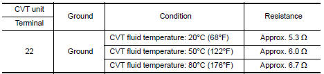
Is the inspection result normal?
YES >> INSPECTION END
NO >> There is a malfunction of low brake solenoid valve. Replace transaxle assembly. Refer to TM "Removal and Installation".
 P0998 Shift solenoid F
Other materials:
Trunk lid
WARNING
Do not drive with the trunk lid open. This
could allow dangerous exhaust gases
to be drawn into the vehicle. For additional
information, refer to "Exhaust
gas (carbon monoxide)" in the "Starting
and driving" section of this manual.
Closely supervise children when they
are a ...
Positive crankcase ventilation
Inspection
1.CHECK PCV VALVE
With engine running at idle, remove PCV valve from rocker cover. A
properly working valve makes a hissing noise as air passes through
it. A strong vacuum should be felt immediately when a finger is
placed over valve inlet.
Is the inspection result normal?
YES &g ...
Categories
- Manuals Home
- Nissan Versa Owners Manual
- Nissan Versa Service Manual
- Video Guides
- Questions & Answers
- External Resources
- Latest Updates
- Most Popular
- Sitemap
- Search the site
- Privacy Policy
- Contact Us

0.0062