Nissan Versa (N17): C1121, C1123, C1125, C1127 ABS Out valve system
DTC Logic
DTC DETECTION LOGIC 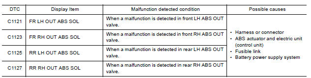
DTC CONFIRMATION PROCEDURE
1.CHECK SELF DIAGNOSTIC RESULT
With CONSULT.
- Turn ignition switch ON.
- Perform self diagnostic result.
Is DTC C1121, C1123, C1125 or C1127 detected?
YES >> Proceed to diagnosis procedure. Refer to BRC "Diagnosis Procedure".
NO >> Inspection End.
Diagnosis Procedure
Regarding Wiring Diagram information, refer to BRC "Wiring Diagram".
1.CONNECTOR INSPECTION
- Turn ignition switch OFF.
- Disconnect ABS actuator and electric unit (control unit) connector.
- Check connector and terminals for deformation, disconnection, looseness or damage.
Is the inspection result normal?
YES >> GO TO 2
NO >> Repair or replace as necessary.
2.CHECK ABS ACTUATOR AND ELECTRIC UNIT (CONTROL UNIT) BATTERY POWER SUPPLY
Check voltage between ABS actuator and electric unit (control unit) connector
E33 terminal 25 and ground. 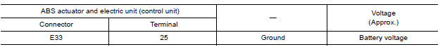
Is the inspection result normal?
YES >> GO TO 3.
NO >> Repair or replace malfunctioning components.
3.CHECK ABS ACTUATOR AND ELECTRIC UNIT (CONTROL UNIT) GROUND CIRCUIT
Check continuity between ABS actuator and electric unit (control unit)
connector E33 terminals 13, 38 and
ground. 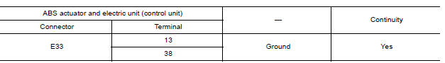
Is the inspection result normal?
YES >> Replace ABS actuator and electric unit (control unit). Refer to BRC "Removal and Installation".
NO >> Repair or replace malfunctioning components.
 C1120, C1122, C1124, C1126 ABS In valve
system
C1120, C1122, C1124, C1126 ABS In valve
system
Other materials:
RearView Monitor (if so equipped)
1. CAMERA button (models with navigation)
WARNING
Failure to follow the warnings and instructions
for proper use of the Rear-
View Monitor system could result in serious
injury or death.
RearView Monitor is a convenience feature
and is not a substitute for proper
backing. Always ...
Vehicle Dynamic Control (VDC) system (if so equipped)
The VDC system uses various sensors to monitor
driver inputs and vehicle motion. Under certain
driving conditions, the VDC System helps to perform
the following functions:
Controls brake pressure to reduce wheel
slip on one slipping drive wheel so power is
transferred to a non slipping drive w ...
Categories
- Manuals Home
- Nissan Versa Owners Manual
- Nissan Versa Service Manual
- Video Guides
- Questions & Answers
- External Resources
- Latest Updates
- Most Popular
- Sitemap
- Search the site
- Privacy Policy
- Contact Us

0.0058